Disk drive head suspension with spring rails for base plate microactuation

a technology of microactuation and drive head, which is applied in the direction of magnetic recording, data recording, instruments, etc., can solve the problems of becoming increasingly difficult for the motor and servo control system to quickly and accurately position the drive head

Inactive Publication Date: 2006-03-21
INTRI PLEX (THAILAND) LTD
View PDF18 Cites 59 Cited by
  • Summary
  • Abstract
  • Description
  • Claims
  • Application Information

AI Technical Summary

Benefits of technology

[0009]The present invention also provides a head suspension assembly including a base plate of the present invention. The head suspension assembly also includes a load beam mounted to the load beam mounting region, with the...

Problems solved by technology

As track density increases, however, it becomes increasingly difficult for the motor and se...

Method used


Image

  • Disk drive head suspension with spring rails for base plate microactuation
  • Disk drive head suspension with spring rails for base plate microactuation
  • Disk drive head suspension with spring rails for base plate microactuation

Examples


Embodiment Construction

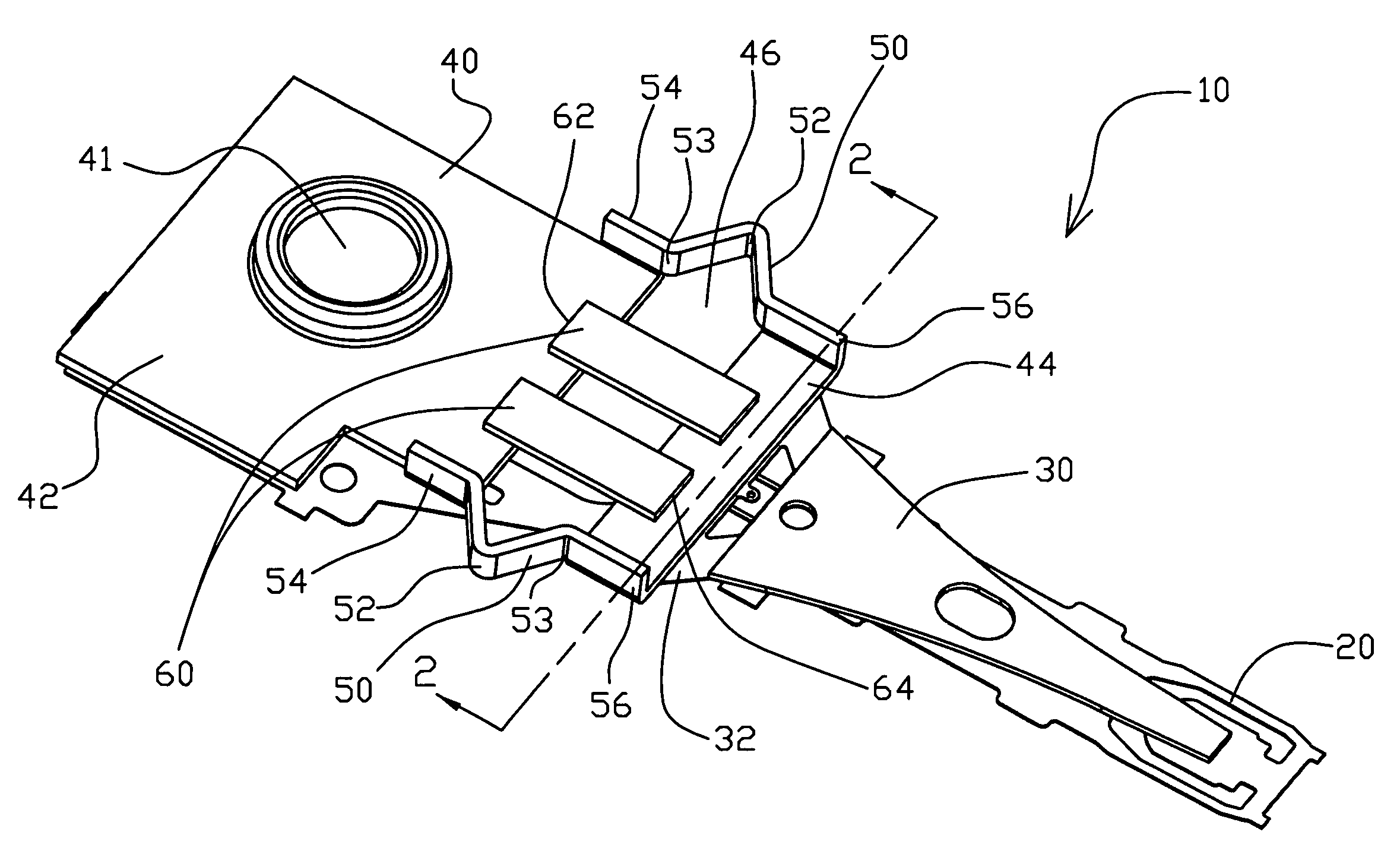
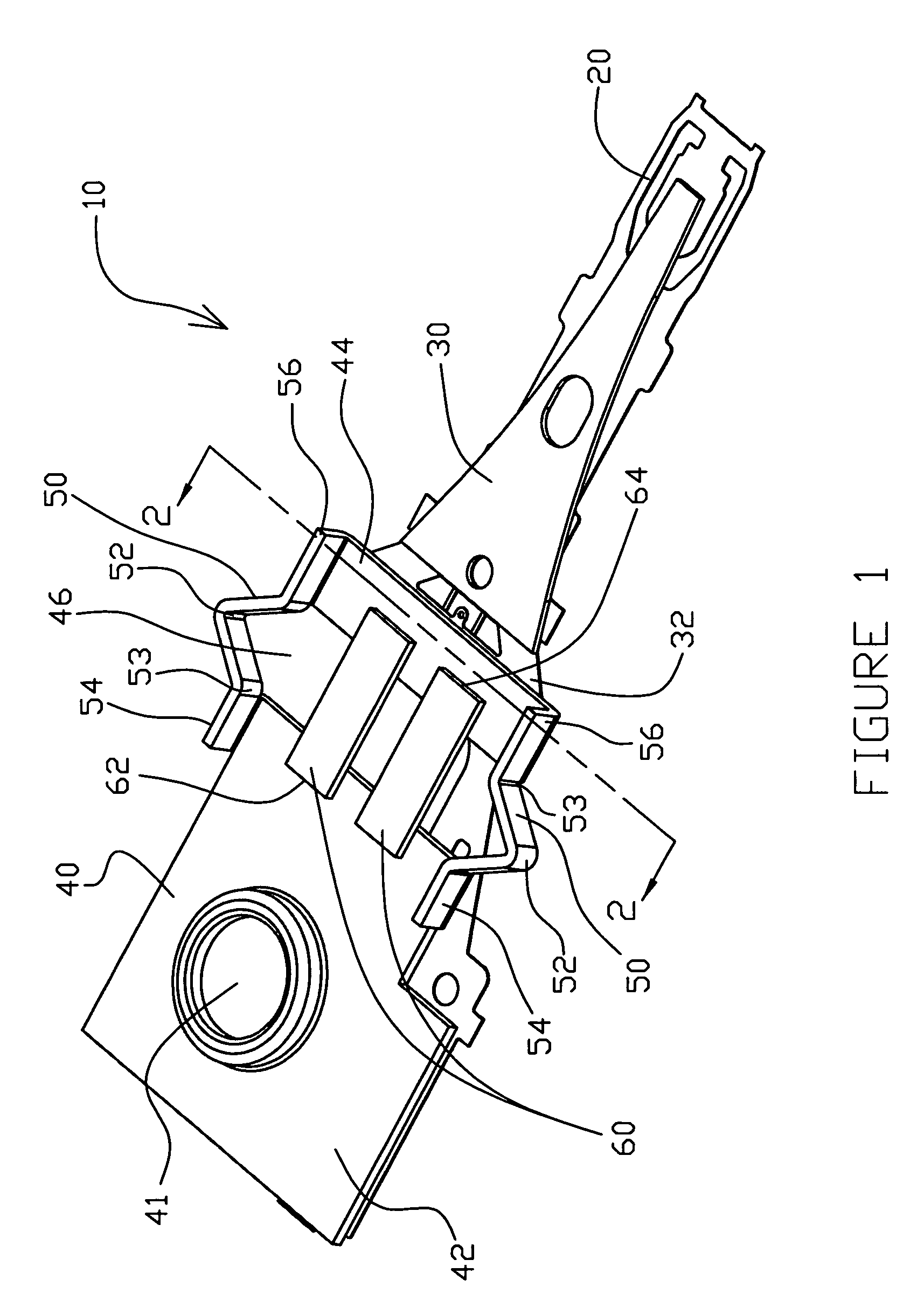
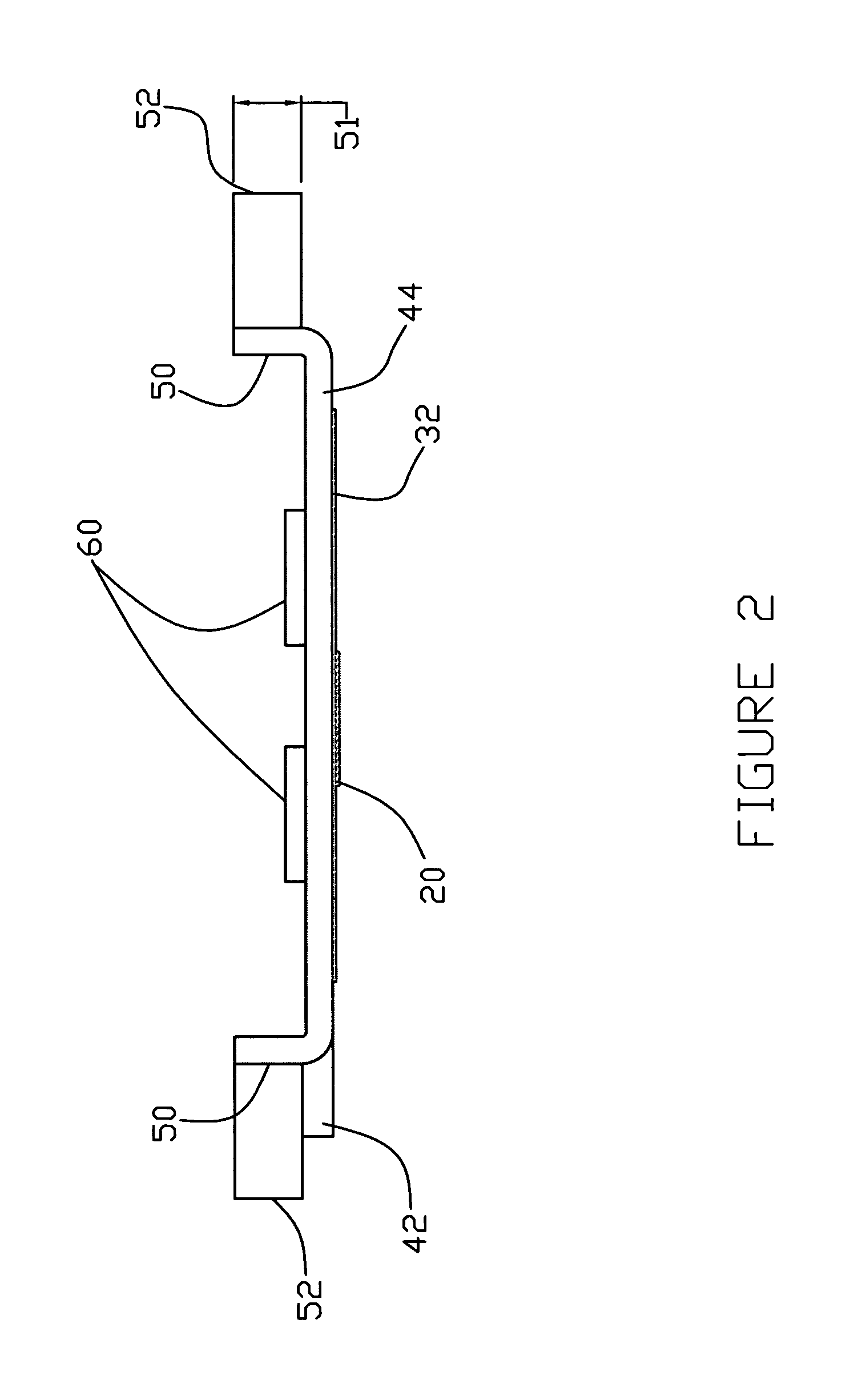
[0016]With reference to the attached Figures, it is to be understood that like components are labeled with like numerals throughout the several Figures. Referring now to FIGS. 1 and 2, a head suspension assembly 10 including a flexure 20, a load beam 30 and a base plate 40, is shown. In this embodiment, the base plate 40 includes a drive mounting region 42 and a load beam mounting region 44, which are connected by side rails 50, and a bore 41 for mounting to the head suspension drive or actuator. The load beam 30 mounts to the load beam mounting region 44 at a load beam mount 32 that may function as a separate spring region. As used herein, the term base plate refers to any member providing a connection between the suspension and a primary actuator for the disk drive. Although shown as a swage plate type base plate, it is to be understood that a unamount-style arm or other suitable member may also be used in the present invention and are included within use of the term base plate.

[0...


PUM


Abstract

A base plate for a head suspension assembly having a pair of side rails including spring portions. The base plate including first and second portions connected by the pair of side rails and separated by an opening, with the spring portions positioned adjacent to the opening. The base plate configured to receive a microactuator spanning the opening with the microactuator causing relative movement between the first and second portions of the base plate at the spring portions of the side rails, so as to provide fine manipulation of a head slider mounted to the head suspension assembly.

Description

[0001]The present application claims priority to U.S. provisional application Ser. No. 60 / 307,448, entitled DISK DRIVE HEAD SUSPENSION WITH SPRING RAILS FOR BASE PLATE MICROACTUATION, filed on Jul. 24, 2001, which is herein incorporated by reference in its entirety.BACKGROUND OF THE INVENTION[0002]In a dynamic rigid disk storage device, a rotating disk is employed to store information. Rigid disk storage devices typically include a frame to provide attachment points and orientation for other components, and a spindle motor mounted to the frame for rotating the disk. A read / write head is formed on a “head slider” for writing and reading data to and from the disk surface. The head slider is supported and properly oriented in relationship to the disk by a head suspension that provides both the force and compliance necessary for proper head slider operation. As the disk in the storage device rotates beneath the head slider and head suspension, the air above the disk also rotates, thus c...

Claims


Application Information

Patent Timeline
IPC IPC(8): G11B5/55
CPCG11B5/4833G11B5/5569G11B5/5552
Inventor BJORSTROM, JACOB D.DANIELSON, REID C.
Owner INTRI PLEX (THAILAND) LTD
Why Eureka
Try Eureka