Proximity sensor for level sensing

a level sensor and proximity sensor technology, applied in the field of level sensing, can solve the problems of increasing the potential for fluid spillage, inability to readily be used remotely, and general inability to provide remote level indication

Active Publication Date: 2006-03-28
TOUCHSENSOR TECH
View PDF15 Cites 84 Cited by
  • Summary
  • Abstract
  • Description
  • Claims
  • Application Information

AI Technical Summary

Problems solved by technology

Whereas sight glasses can provide highly accurate, visual indication of fluid level, they generally must be located at or near the tank whose fluid level is to be measured, and they generally cannot be used to provide remote level indication.
Further, the top and bottom of a sight glass generally must be plumbed into the side wall of the tank whose fluid level is to be measured, increasing the potential for fluid spills.
Measuring sticks, such as dip sticks, also require presence at the tank whose fluid level is to be measured, and they cannot readily be used remotely.
Measuring sticks have the further disadvantage that they must be physically inserted into the fluid whose level they are measuring.
As such, their use increases the chance of contaminating the fluid being measured.
However, they generally provide only local indication and are not readily adapted for providing remote indication.
Further, they are prone to failure due to vibration, exposure to the elements, and other harsh environmental conditions during ordinary use.
As such, devices of this nature place constraints on tank design and packaging efficiency.
Such units typically would not give accurate data when used in tanks with irregular cross sections.
Although multiple units could be used to mitigate this concern, such use would add cost, complexity, and might not be feasible in all situations due to space constraints.
However, conventional field effect sensors are not sensitive to certain other fluid types, for example, hydrocarbons such as gasoline.

Method used


Image

  • Proximity sensor for level sensing
  • Proximity sensor for level sensing
  • Proximity sensor for level sensing

Examples


Embodiment Construction

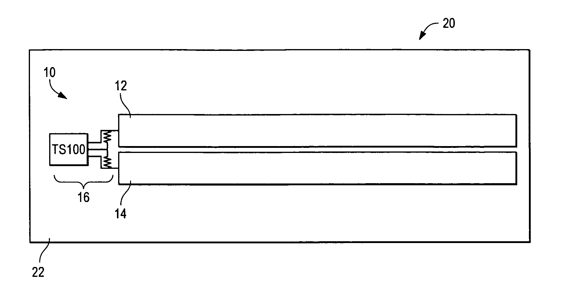
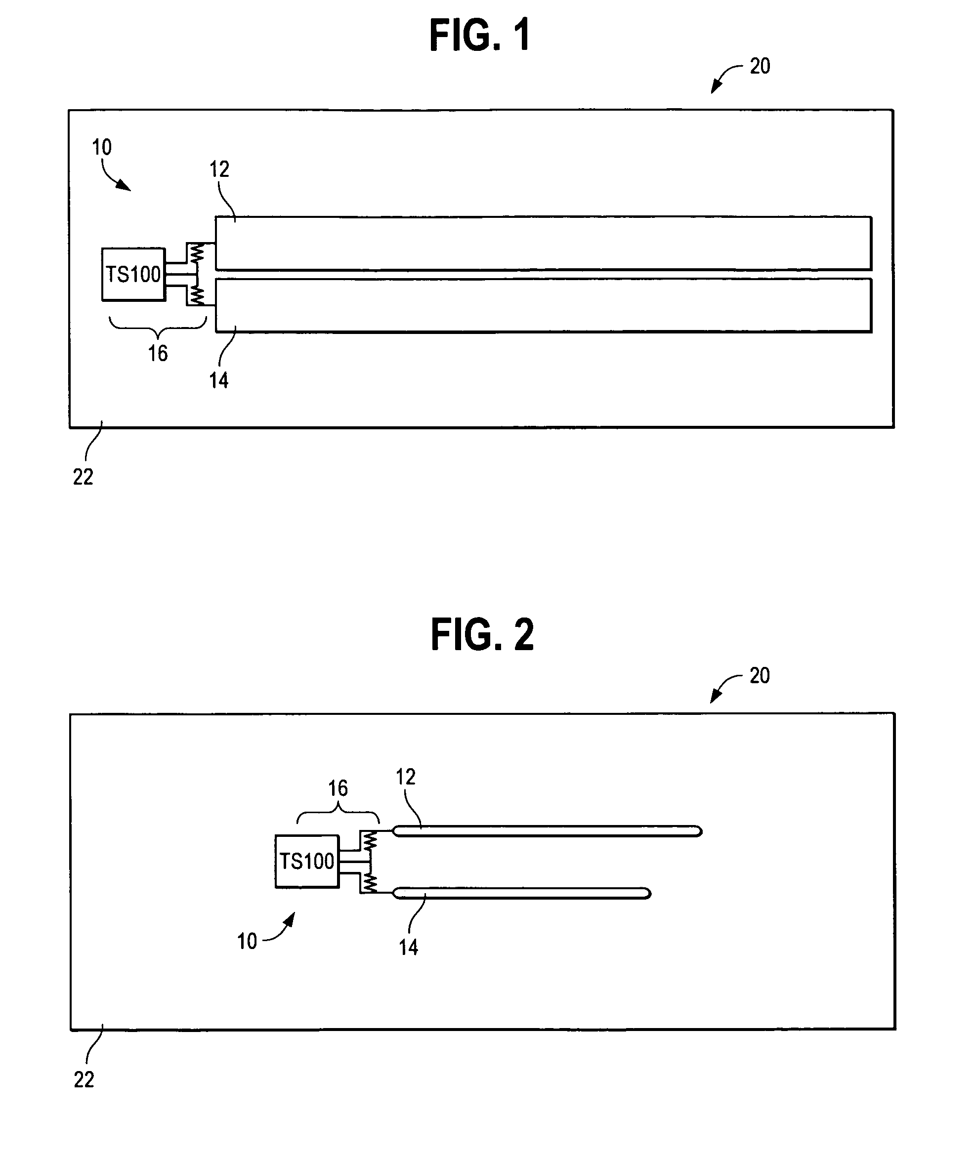
[0013]FIG. 1 illustrates a field effect sensor 10 located on the side wall 22 of a tank 20 containing a fluid, such as the gas tank of an automobile. In other embodiments, tank 20 could contain multiple fluids or a powder. Preferably, sensor 10 is located on the outside of tank 20, but also could be located on the inside of tank 20. Alternatively, sensor 10 could be embedded within the side wall 22 of tank 20.

[0014]Sensor 10 includes first and second, substantially parallel, electrodes 12,14 coupled to a control circuit 16. Preferably, control circuit 16 is embodied as the control circuit provided with the TS100 sensor available from TouchSensor Technologies, LLC of Wheaton, Ill. Many of the design and operating principles of the TS100 sensor are described in U.S. Pat. Nos. 6,230,282 and 6,713,897 and related U.S. patent application Ser. Nos. 10 / 272,377 10 / 725,908, the disclosures of which are incorporated herein by reference.

[0015]Electrodes 12,14 differ from conventional sensor el...


PUM


Abstract

A field effect sensor is adapted for use in sensing level of fluids and powders. The sensor uses elongated, parallel electrodes disposed on or within the side wall of a tank. The longitudinal axes of the electrodes are parallel to the surface of fluid or powder contained in the tank.

Description

CROSS-REFERENCE TO RELATED APPLICATIONS[0001]This application claims priority from U.S. Provisional Patent Application Ser. No. 60 / 464,439, entitled “Electrode Designs for Sensing Level of Low Dielectric Constant Fluids and Substances,” filed on Apr. 22, 2003, the disclosure of which is incorporated herein by reference.BACKGROUND OF THE INVENTION[0002]1. The Technical Field[0003]The present invention is directed generally to level sensing. More particularly, the present invention is directed to proximity sensors having electrodes adapted for sensing level of fluids and other substances.[0004]2. The Prior Art[0005]It often is convenient or necessary to know the level of fluid in a tank or other container. Known means for doing so include sight glasses, measuring sticks, floats with mechanical linkages which indicate level and floats connected to electrical sending devices. Though widely used, these types of level sensing equipment are not without shortcomings. Whereas sight glasses c...

Claims


Application Information

Patent Timeline
Patent Type & Authority Patents(United States)
IPC IPC(8): G01F23/00G01F23/26
CPCG01F23/261G01F23/268G01F23/266G01F23/26G01F23/00G01F23/24
Inventor ZIELINSKI, MICHAEL R.TAYLOR, MICHAEL JON
Owner TOUCHSENSOR TECH
Why Eureka
Try Eureka