Draw latch having kick-out catch

a technology of latches and latches, which is applied in the direction of couplings, carpet fasteners, manufacturing tools, etc., can solve the problems that the lever cannot be easily used to easily rotate the latches relative to or away from the base, and achieve the effect of easy disengagement of the latches and less force on the latches

Inactive Publication Date: 2006-03-28
ASMITH MFG
View PDF13 Cites 18 Cited by
  • Summary
  • Abstract
  • Description
  • Claims
  • Application Information

AI Technical Summary

Benefits of technology

[0008]The primary objective of the present invention is to provide a draw latch including a catch that may be kicked out by a lever which may act or actuate onto the catch in both directions parallel to and perpendicular to the catch, to easily disengage the catch from a panel member and to separate the catch from the panel member with less force.
[0011]The catch includes a lock nut threaded onto the threaded shank and engageable with the end panel of the bracket, for solidly locking the threaded shank of the catch to the bracket. The bracket includes an opening formed therein for allowing the threaded shank of the catch to be seen through the opening of the bracket. The actuator of the lever is preferably offset from the side flaps thereof for effectively actuating onto the cam member.

Problems solved by technology

However, when the lever is rotated relative to the base to engage with and to actuate or to rotate the catch relative to the base, the lever applies a force against the catch in an actuating direction parallel to the catch, but may not apply a force against the catch in an actuating direction perpendicular to the catch, in addition, the lever is acted onto the catch at an end position on the other side of the pin, such that the lever may have to apply a greater force to kick out the catch, and such that the lever may not be used to easily rotate the catch relative to or away from the base.

Method used


Image

  • Draw latch having kick-out catch
  • Draw latch having kick-out catch
  • Draw latch having kick-out catch

Examples


Embodiment Construction

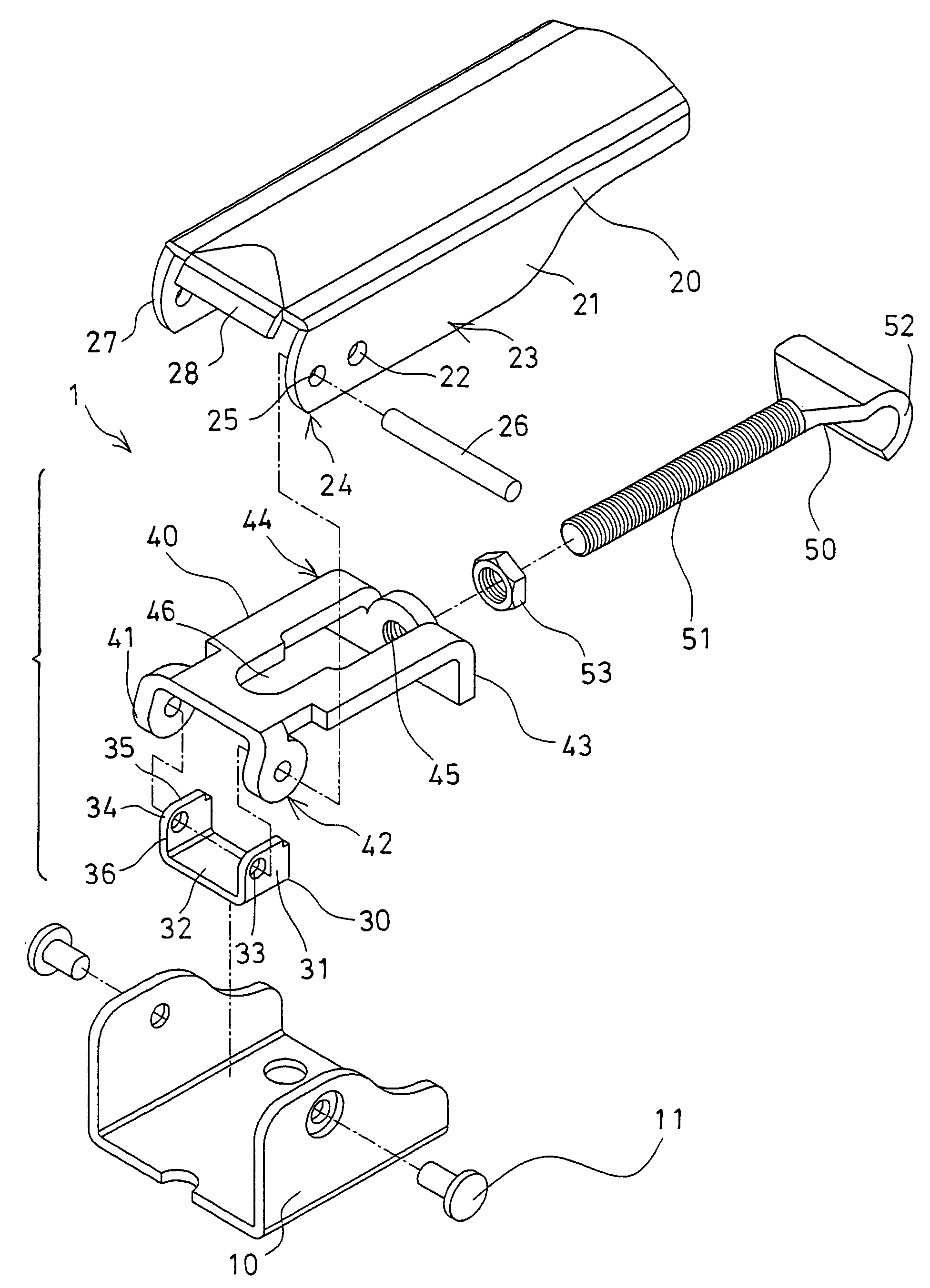
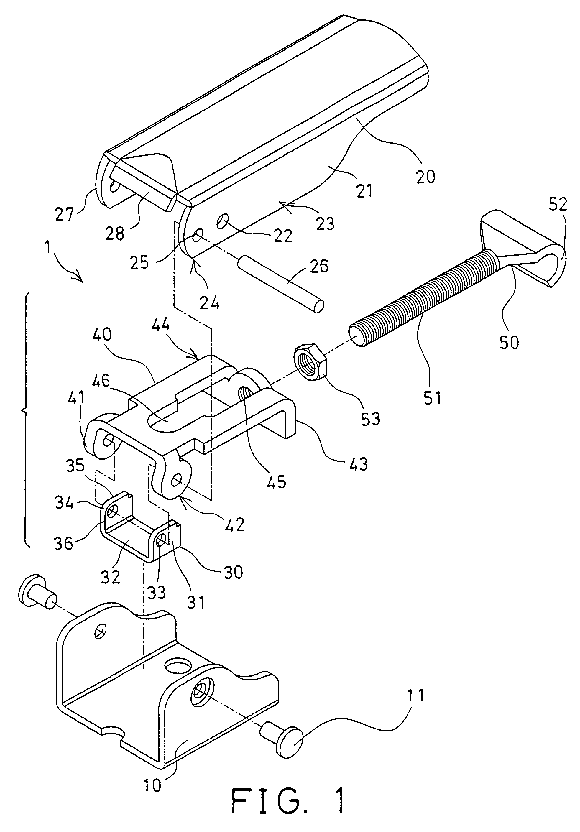
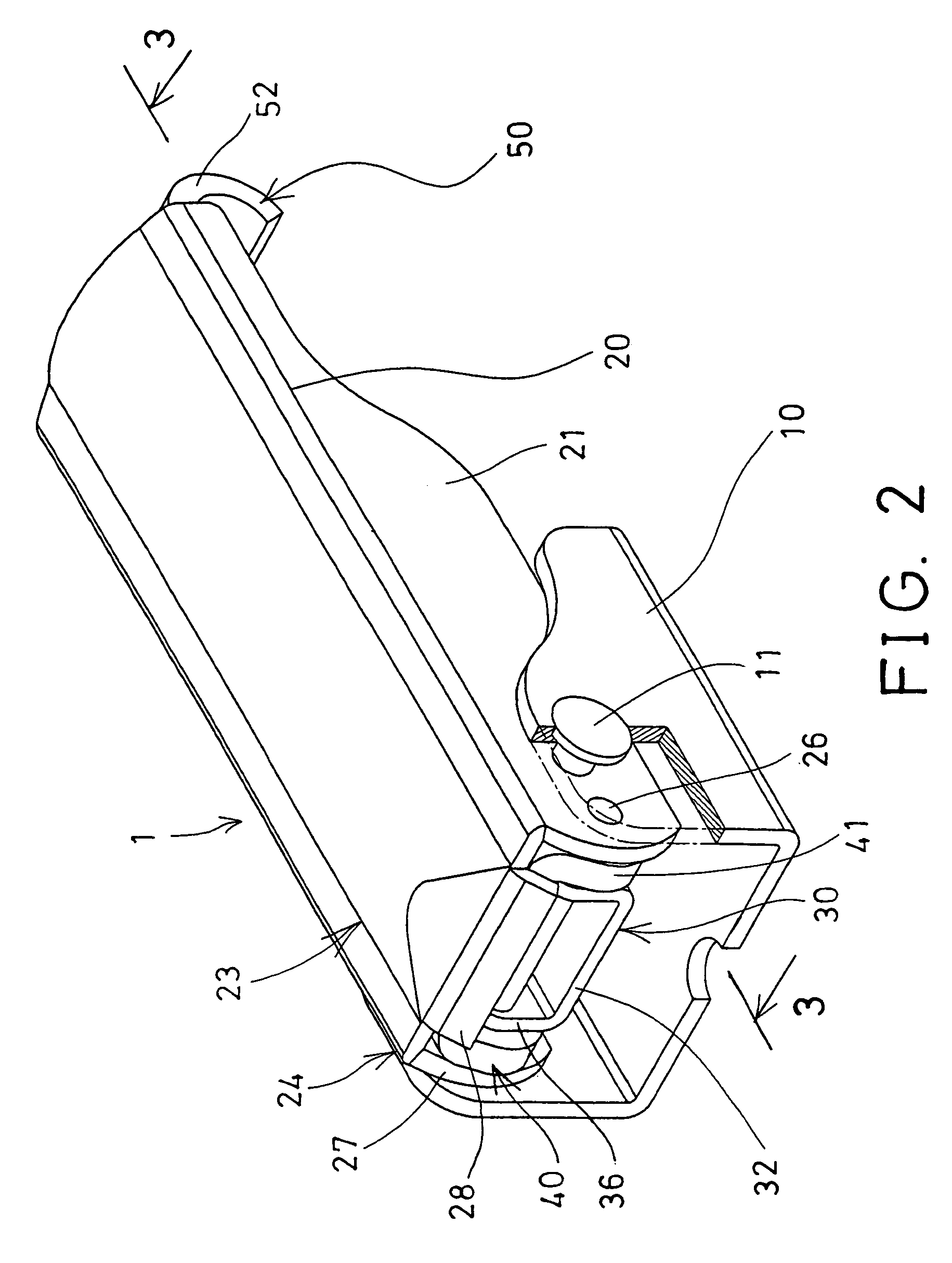
[0017]Referring to the drawings, and initially to FIGS. 1–3, a draw latch 1 in accordance with the present invention is provided for attaching to two panel members 90, 91 of typical doors, windows, cabinets, boxes, or the like, and for detachably securing or locking or latching the panel members 90, 91 together. For example, the draw latch 1 comprises a base member 10 for securing to one of the panel members 90 with fasteners (not shown) or the like. The other panel member 91 includes a typical U-shaped keeper 92 secured thereto for engaging with the draw latch 1, and for allowing the draw latch 1 to be used to latch the panel members 90 and 91 together.

[0018]The draw latch 1 further includes a lever 20 pivotally or rotatably attached to the base member 10 with a pivot axle 11. For example, the lever 20 includes two side flaps 21 extended therefrom and parallel to each other, and each having a hole 22 formed in an intermediate portion 23 thereof and located close to one end 24 there...


PUM


Abstract

A draw latch includes a base member and a keeper secured to two panel members, a lever having two side flaps rotatably attached to the base member and having an actuator extended from one end, a cam member and a bracket rotatably attached to the side flaps of the lever. The bracket includes an end panel for threading to a catch which has a hook for engaging with the keeper. The cam member includes two side plates extended from a bottom plate and each having a horizontal surface for engaging with the bracket, to allow the actuator to actuate onto the cam member and then to actuate onto the bracket in a direction perpendicular to the bracket via the horizontal surfaces of the cam member.

Description

BACKGROUND OF THE INVENTION[0001]1. Field of the Invention[0002]The present invention relates to a draw latch, and more particularly to a draw latch having a catch that may be kicked out by a lever with less force.[0003]2. Description of the Prior Art[0004]Various kinds of typical catches or locks or latches, such as draw latches have been developed and provided for attaching to two panel members or elements of doors, windows, or the like, and for easily and quickly locking or latching the panel members of the doors or the windows or the like together, and comprise a base member for attaching to one of the door panels or windows, and a catch member for latching or catching to the other door panel or window.[0005]For example, U.S. Pat. No. 5,478,125 to Gromotka discloses one of the typical draw latches comprising a base attached to a panel member of the doors or windows, a catch member pivotally or rotatably attached to the base, and a lever also pivotally or rotatably attached to th...

Claims


Application Information

Patent Timeline
Patent Type & Authority Patents(United States)
IPC IPC(8): E05C19/12
CPCE05C19/14Y10T403/595Y10S292/49Y10T292/0871Y10T292/0917Y10T292/216
Inventor CHIANG, CHING HUA
Owner ASMITH MFG
Why Eureka
Try Eureka