
Power tool with integral gripping member

a technology of gripping member and power tool, which is applied in the field of power tools, can solve the problems of general cold, hard or slippery housing, and uncomfortable feeling for the end user

Inactive Publication Date: 2006-03-28
BLACK & DECKER INC
View PDF28 Cites 24 Cited by
  • Summary
  • Abstract
  • Description
  • Claims
  • Application Information

AI Technical Summary

Benefits of technology

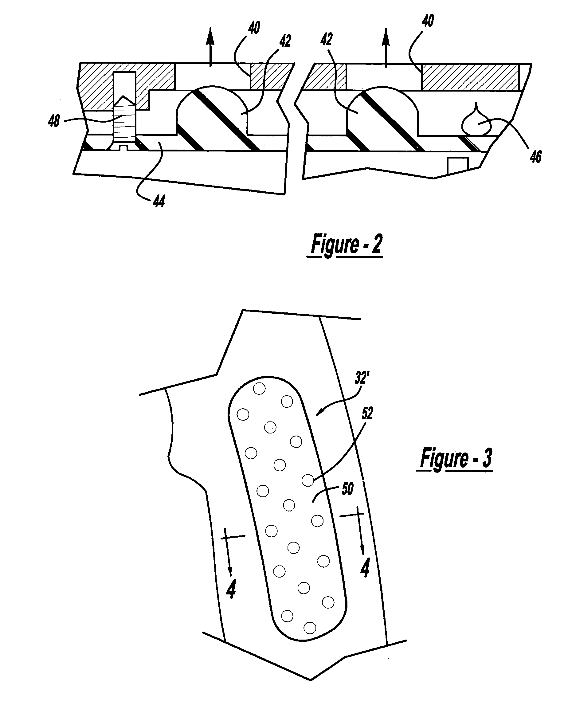
[0006]In accordance with the third aspect of the invention, a power tool comprises a pair of members coupling with one another forming a housing wall. The housing wall defines a cavity. The housing wall has an outer and an inner surface. At least one aperture extends through at least one housing member. A gripping member is positioned to be contacted by the user when the user contacts the outer surface of the wall of the at least one housing member. At least one securement member is coupled with the gripping member. The securement member extends through the at least one aperture to secure the gripping surface to the outer surface of the housing. A motor is positioned in the housing cavity. Also, an output is coupled with the motor and projects from the housing. A power source is coupled with the motor. An activation member is coupled with the motor and the power source to energize and de-energize the power tool.

Problems solved by technology

In power tools which have metallic housings, the housing is generally cold, hard or slippery.
This feel is uncomfortable to the end user.
Thus, metal housings, while having several desired properties, have the shortcomings that they do not provide the user with the intended feel.

Method used


Image

  • Power tool with integral gripping member
  • Power tool with integral gripping member
  • Power tool with integral gripping member

Examples


Embodiment Construction

[0015]The following description of the preferred embodiment(s) is merely exemplary in nature and is in no way intended to limit the invention, its application, or uses.

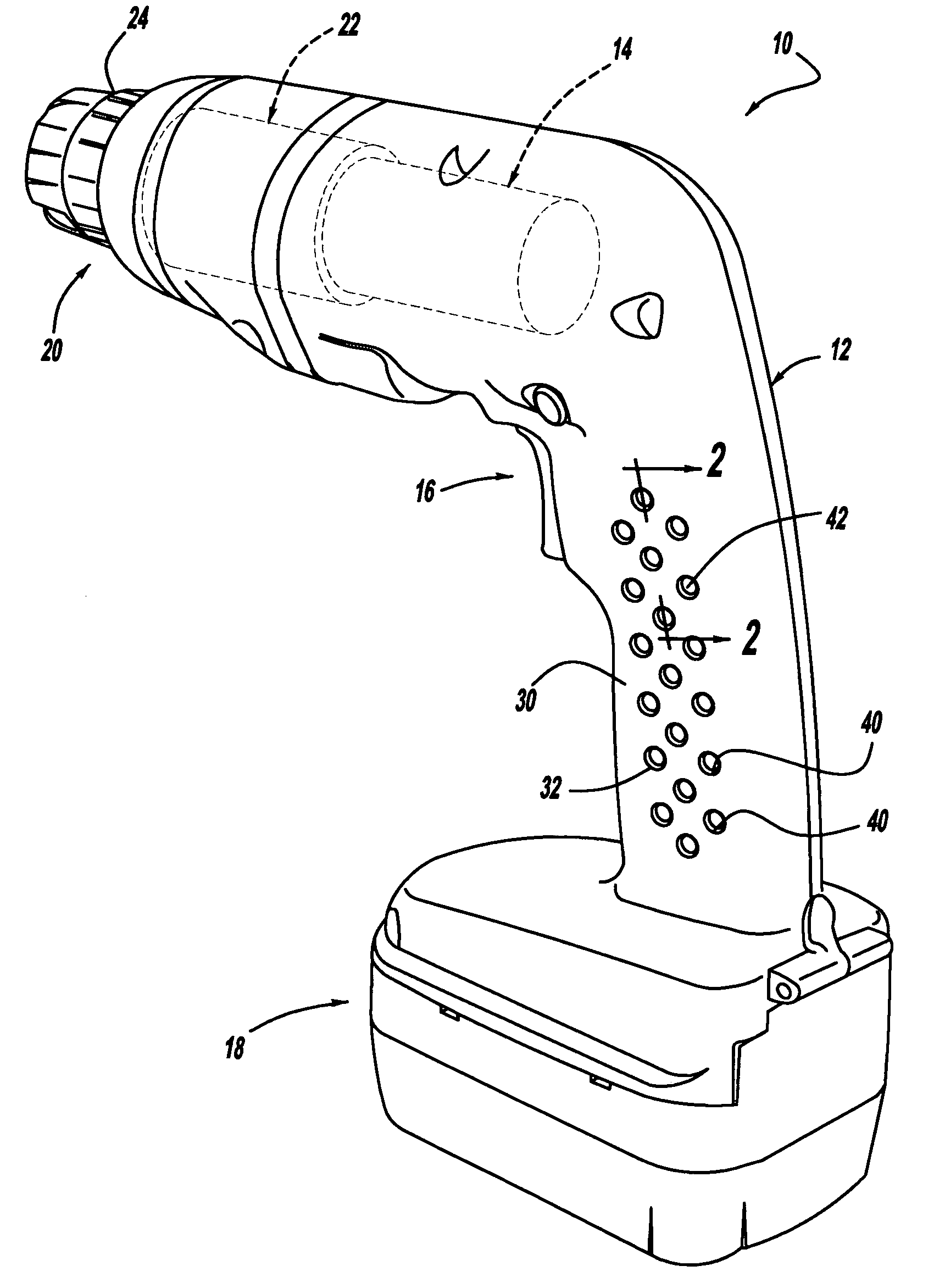
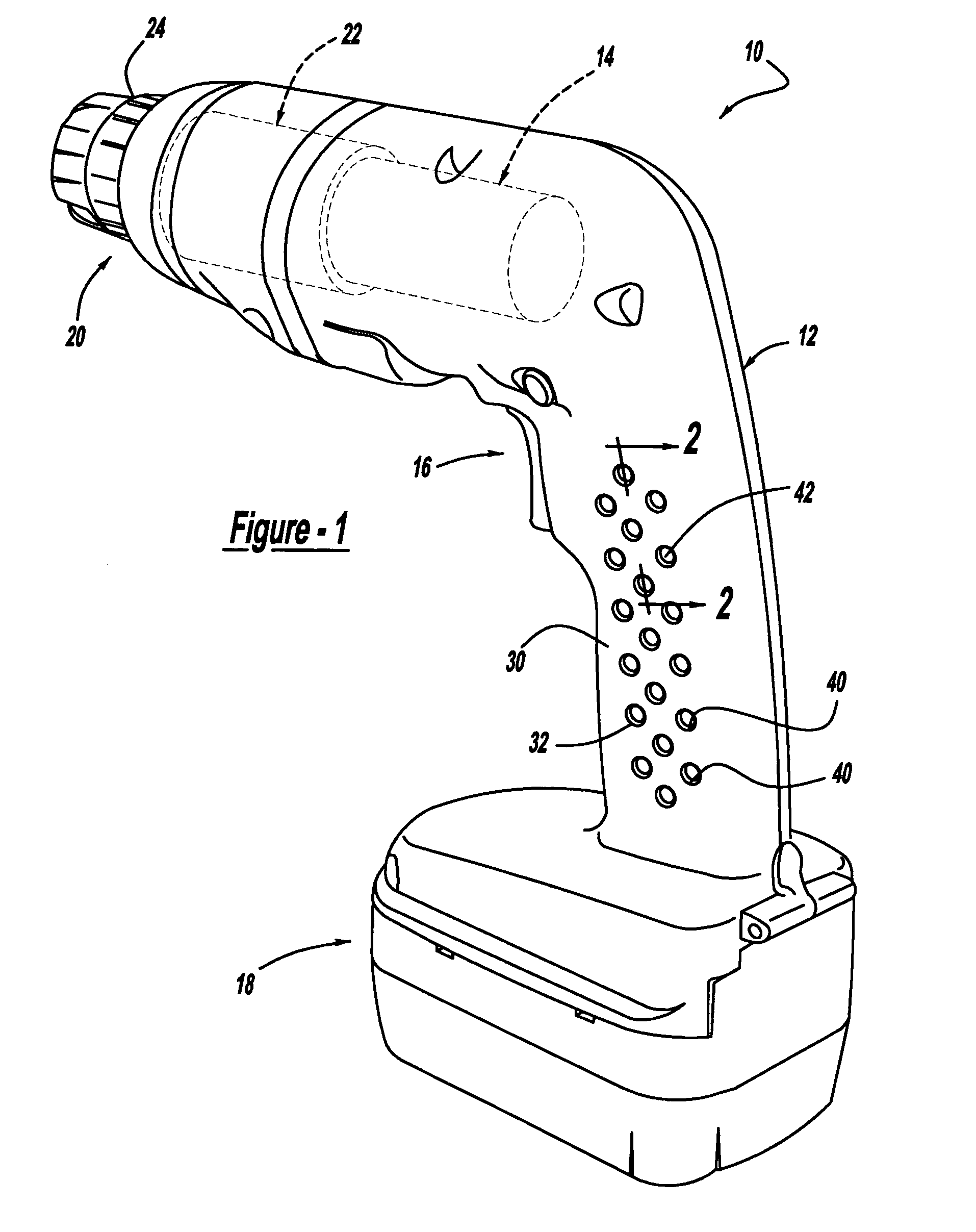
[0016]Turning to FIG. 1, a power tool in accordance with the present invention is illustrated and designated with the reference numeral 10. The power tool 10 is illustrated as a drill; however, any type of power tool such as screwdriver, sander, rotary tool, clippers, saw or the like which utilizes an electric motor and includes a housing may be used with the present invention. The power tool 10 includes a housing 12 which surrounds a motor 14. An activation member 16 is coupled with the motor 14 as well as with the power source 18. The power source 18 may be a battery (DC current) as shown or the power tool may have a power cord (AC current). The motor 14 is coupled with an output 20 which may include a transmission 22 and a chuck 24 to retain a tool (not shown) with the drill.

[0017]The housing 12 includes a handle p...


PUM

PropertyMeasurementUnit
Elastomericaaaaaaaaaa

Abstract

A power tool has a housing with at least one aperture in the housing. A gripping member is positioned with respect to the outer surface of the housing such that the gripping member is contacted by a user when the power tool is used. At least one member is coupled with the gripping member. The at least one member extends through the at least one housing aperture to enable the gripping member to be positioned with respect to the outer surface of the housing.

Description

FIELD OF THE INVENTION[0001]The present invention relates to power tools and, more specifically, to power tool housings with integral gripping members.BACKGROUND OF THE INVENTION[0002]All electric power tools utilize housings which include gripping surfaces. The gripping surface enables the user to manipulate the power tool for its intended purpose. In power tools which have metallic housings, the housing is generally cold, hard or slippery. This feel is uncomfortable to the end user. Thus, metal housings, while having several desired properties, have the shortcomings that they do not provide the user with the intended feel.[0003]The present invention provides the art with an improved power tool housing. The housing includes a gripping surface which provides the user with the desired feel. Preferably, the invention is utilized in a metallic tool housing.SUMMARY OF THE INVENTION[0004]In accordance with a first aspect of the invention, a tool housing includes at least one member inclu...

Claims


Application Information

Patent Timeline
IPC IPC(8): B23B45/00B25F5/00B25F5/02
CPCB25F5/006B25F5/02Y10S16/19Y10T16/476Y10T408/65Y10T16/466Y10T408/96
Inventor COOPER, VINCENT P.
Owner BLACK & DECKER INC
Learn More