Self-pumping hydropneumatic suspension strut

a technology of hydropneumatic suspension and self-pumping, which is applied in the direction of shock absorbers, mechanical equipment, transportation and packaging, etc., can solve problems such as acted upon, and achieve the effect of free of choking

Inactive Publication Date: 2006-04-04
ZF FRIEDRICHSHAFEN AG
View PDF6 Cites 19 Cited by
  • Summary
  • Abstract
  • Description
  • Claims
  • Application Information

AI Technical Summary

Benefits of technology

[0008]This embodiment form has the advantage that the flow connection proceeding from the pump chamber to the low-pressure chamber is arranged directly in the intermediate wall and is accordingly no longer influenced by the high pressure of the high-pressure chamber; further, only one suction tube must be received in a bore hole of the intermediate wall.
[0011]Further, the intermediate wall is provided with an annular projection which projects into the low-pressure chamber so as to be sealed. This is advantageous in that the intermediate wall is rigidly constructed up to the pump rod fastening and has a bore hole extending radially in the direction of the pump rod. Proceeding from the low-pressure chamber, a stepped bore hole opens with a smaller diameter into the radial bore hole mentioned above so that only the smaller diameter of the stepped bore hole passes through the area of the adjoining seals and the larger diameter of the stepped bore hole is available to receive the suction tube which is kept short and therefore free of choking. This results in a suspension strut with a small outer tube diameter.
[0012]Another advantage consists in that in an installation position in which the piston rod is arranged at the bottom, the suction tube is pressure-compensated and the high pressure in this installation position has no surface to act upon. Should the suspension strut be installed in such a way that the piston rod is arranged at the top, the suction tube and the outer seal are no longer required because the gas can no longer be sucked out of the low-pressure chamber since it is located in the area of the piston rod guide and not in the area of the intermediate wall.

Problems solved by technology

Further, the suction tube arrangement is not acted upon by the internal pressure of the high-pressure chamber.

Method used


Image

  • Self-pumping hydropneumatic suspension strut
  • Self-pumping hydropneumatic suspension strut
  • Self-pumping hydropneumatic suspension strut

Examples


Embodiment Construction

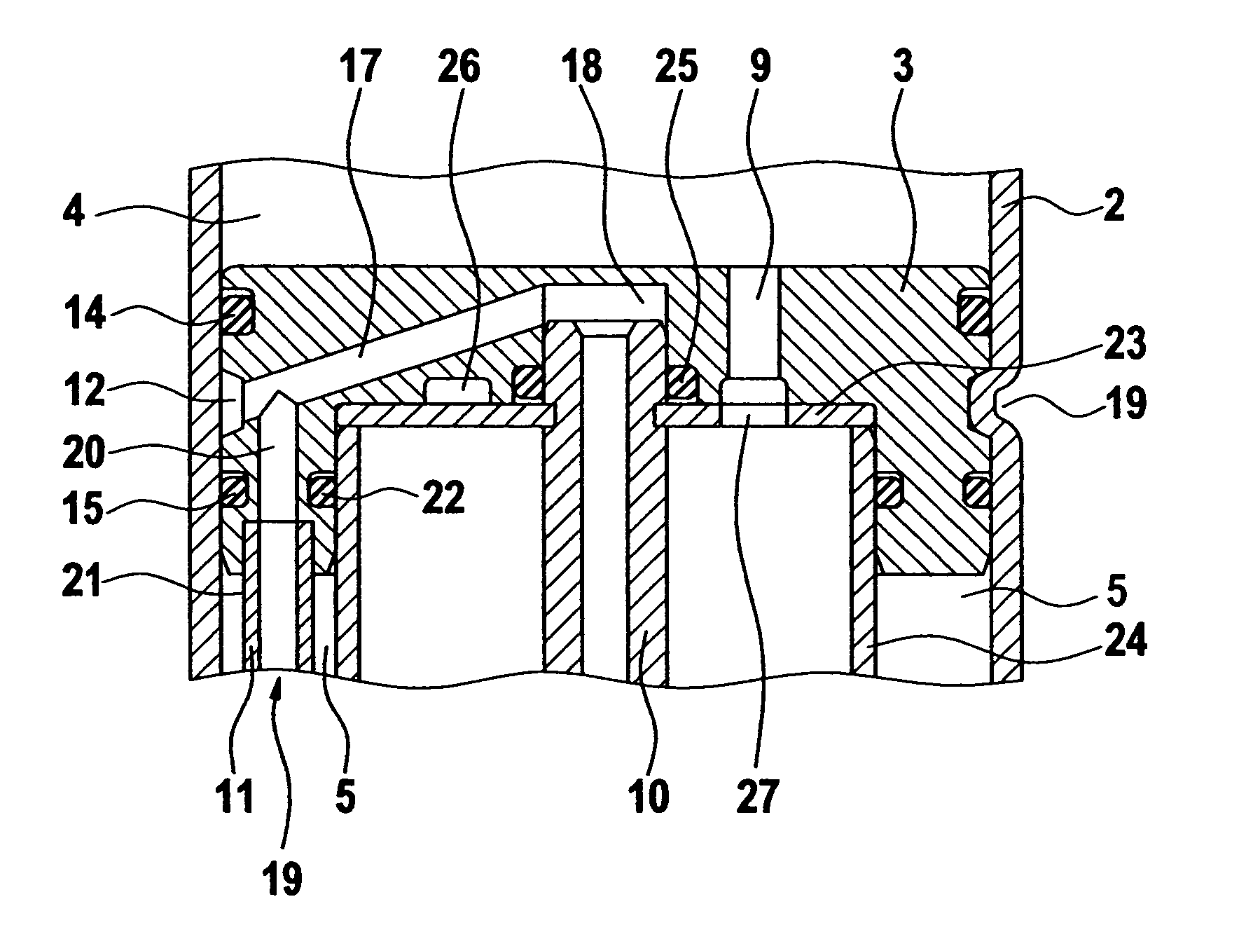
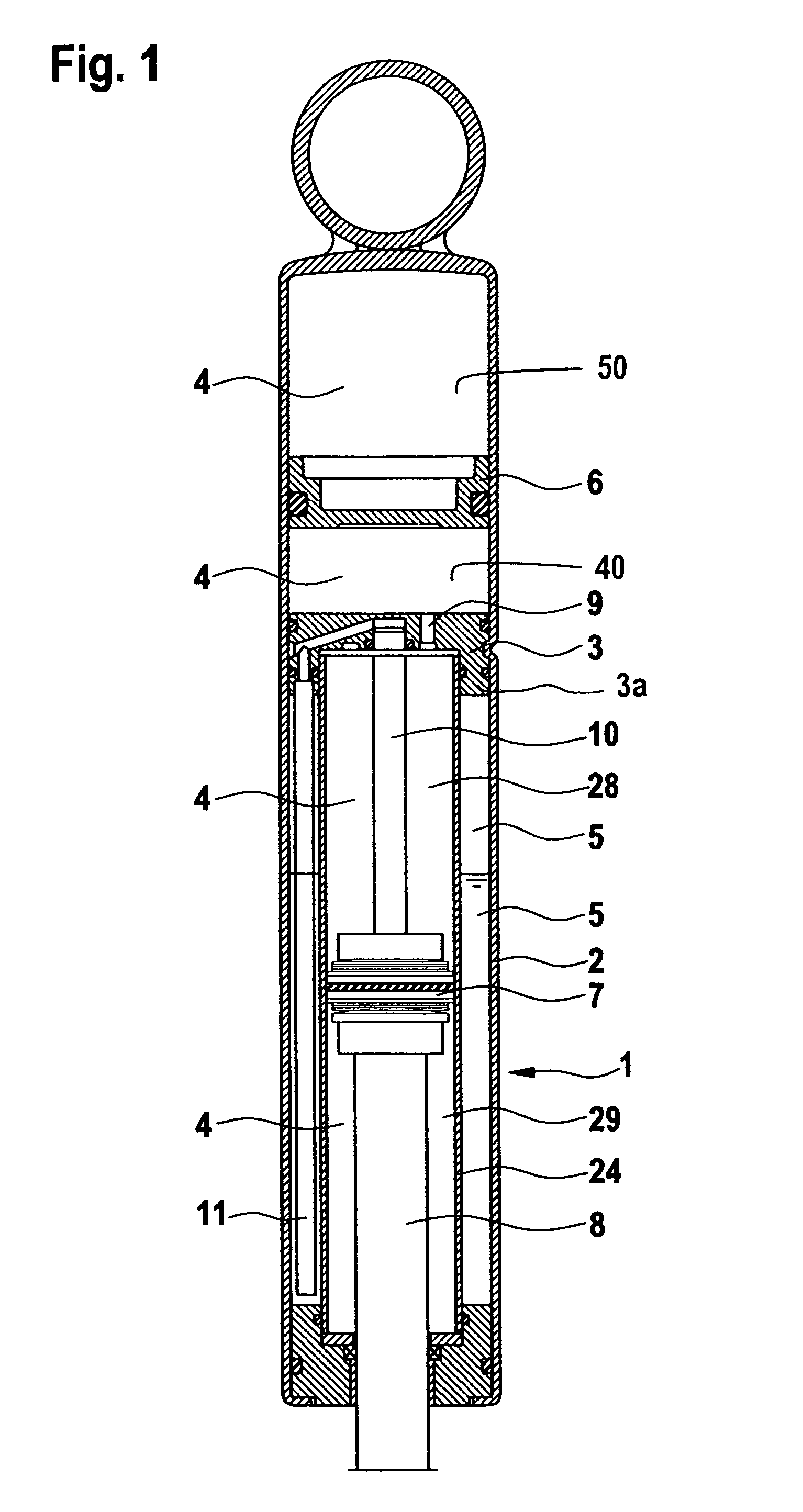
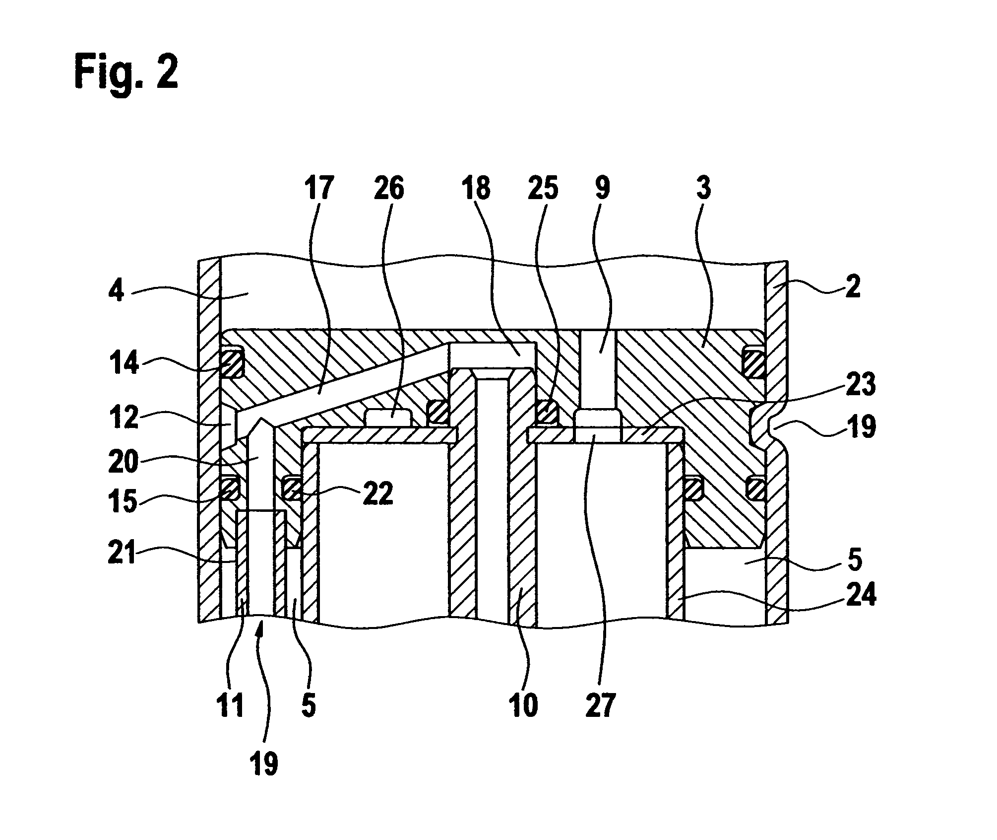
[0026]The suspension strut 1 shown in FIG. 1 substantially comprises the outer tube 2 and the work spaces 28 and 29 which are formed by the damping piston 7 in the work cylinder 24.

[0027]The high-pressure chambers 4 comprise the work spaces 28, 29 and the damping medium reservoir 40 and the high-pressure gas chamber 50, these two areas being divided by the dividing piston 6. The intermediate wall 3 divides the low-pressure chamber 5, which is a reservoir, from the high-pressure chamber 4. The damping medium may be oil for example.

[0028]The self-pumping hydropneumatic suspension strut 1 is shown in FIG. 1 in an installed position in which the piston rod 8 is arranged at the bottom, that is, the piston rod 8 is connected to the wheel suspension, while the outer tube 2 communicates with the vehicle body. The damping medium and pressure gas are accommodated in the low-pressure chamber 5 and in the high-pressure chamber 4. The dividing piston 6 in the high-pressure chamber 4 divides the ...


PUM


Abstract

Self-pumping hydropneumatic suspension strut with internal height control, in particular for motor vehicles with a work cylinder which is filled with oil and is under pressure by at least one gas cushion which is arranged in a high-pressure chamber and which acts as a spring, the work cylinder being divided into two work spaces by a work piston supported by a hollow piston rod, with a piston pump which is driven by the spring movements and conveys oil out of a low-pressure chamber into the work space connected to the high-pressure chamber and connects the work space connected to the high-pressure chamber to the low-pressure chamber by a regulating opening which is closable depending on the position of the work piston in the work cylinder, wherein a flow connection running through an intermediate wall and opening out below the surface of the oil is provided between the pump space and the low-pressure chamber, wherein the flow connection is arranged in the intermediate wall and has at least one bore hole in the area of the low-pressure chamber for receiving a suction tube.

Description

CROSS REFERENCE TO RELATED APPLICATIONS[0001]The application claims priority under 35 U.S.C. §119 to German application DE 103 29 746.4 filed Jul. 2, 2003.BACKGROUND OF THE INVENTION[0002]1. Field of the Invention[0003]The invention is directed to a self-pumping hydropneumatic suspension strut with internal height control, in particular for motor vehicles with a work cylinder which is filled with oil and is under pressure by at least one gas cushion which is arranged in a high-pressure chamber and which acts as a spring, the work cylinder being divided into two work spaces by a work piston supported by a hollow piston rod, with a piston pump which is driven by the spring movements and conveys oil out of a low-pressure chamber into the work space connected to the high-pressure chamber and connects the work space connected to the high-pressure chamber to the low-pressure chamber by a regulating opening which is closable depending on the position of the work piston in the work cylinder...

Claims


Application Information

Patent Timeline
Patent Type & Authority Patents(United States)
IPC IPC(8): F16F9/24B60G11/26F16F9/50B60G15/12B60G17/04B60G17/044
CPCB60G17/044Y10S267/02F16F9/50B60G17/04
Inventor BECK, HUBERT
Owner ZF FRIEDRICHSHAFEN AG
Why Eureka
Try Eureka