Dual-personality extended-USB plug and receptacle with PCI-Express or Serial-At-Attachment extensions

a usb connector and serial extension technology, applied in the field of serial bus connectors, can solve the problems of limiting the use of expresscards, large connectors, and metal contacts of usb connectors with b>4/b> metal contacts that do not support the more complex pci express standard,

Inactive Publication Date: 2006-04-04
SUPER TALENT TECH CORP
View PDF12 Cites 215 Cited by
  • Summary
  • Abstract
  • Description
  • Claims
  • Application Information

AI Technical Summary

Problems solved by technology

Unfortunately, USB connectors with their 4 metal contacts do not support the more complex PCI Express standard.
While the ExpressCard standard is useful for its higher possible data rate, the 26-pin connectors and wider card-like form factor limit the use of ExpressCards.
While SATA and ExpressCard are much higher-speed interfaces than USB, they use larger, bulky connectors while USB has a single, small connector.

Method used


Image

  • Dual-personality extended-USB plug and receptacle with PCI-Express or Serial-At-Attachment extensions
  • Dual-personality extended-USB plug and receptacle with PCI-Express or Serial-At-Attachment extensions
  • Dual-personality extended-USB plug and receptacle with PCI-Express or Serial-At-Attachment extensions

Examples


first embodiment

[0037]FIGS. 4A–I show extended USB connectors and sockets having metal contact pins on both top and bottom surfaces of the pin substrates. In FIG. 4A, the extended connector has plastic housing 76 that the user can grip when inserting the connector plug into a socket. Pin substrate 70 supports metal contact pins 88 on the top surface. Pin substrate 70 is an insulator such as ceramic, plastic, or other material. Metal leads or wires can pass through pin substrate 70 to connect metal contact pins 88 to wires inside plastic housing 76 that connect to the peripheral device.

[0038]Reverse-side metal contact pins 72 are placed in a recess in the bottom side of pin substrate 70 near the tip of the connector plug. Ribs can be added alongside contact pins 72 to further prevent shorting. Reverse-side metal contact pins 72 are additional pins for extended signals such as for PCI-Express signals. Metal leads or wires can pass through pin substrate 70 to connect reverse-side metal contact pins 72...

second embodiment

[0050]FIGS. 5A–H show extended USB connectors and sockets having metal contact pins on just one of the surfaces of the pin substrates. In FIG. 5A, the extended connector has plastic housing 96 that the user can grip when inserting the connector plug into a socket. Pin substrate 90 supports metal contact pins 100, 101 on the top surface. Pin substrate 90 is an insulator such as ceramic, plastic, or other material. Metal leads or wires can pass through pin substrate 90 to connect metal contact pins 100, 101 to wires inside plastic housing 96 that connect to the peripheral device.

[0051]The length of pin substrate 90 is longer than the length L2 of pin substrate 34 in the prior-art USB connector of FIG. 3A. The extension in length can be 2–5 millimeters. Tip-end metal contact pins 101 are located mostly in the extension region beyond L2. Metal cover 93 is a rectangular tube that surrounds pin substrate 90 and has an open end.

[0052]FIG. 5B shows an extended-USB socket having metal contac...

third embodiment

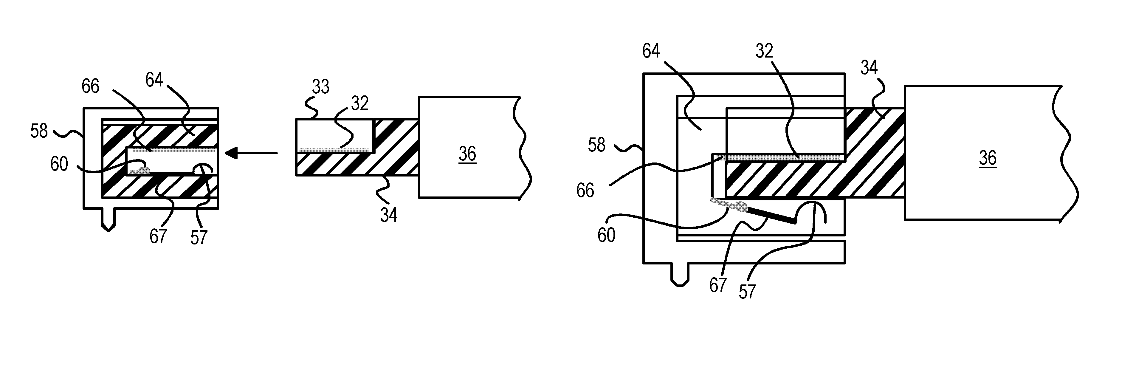
[0062]FIGS. 6A–H show extended-function USB connectors and sockets using extended pins on a pivoting substrate attached to the socket's pin substrate. The length and depth do not have to be extended in this embodiment, or can be extended less than the embodiments of FIGS. 4, 5.

[0063]In FIG. 6A, the connector has plastic housing 56 that the user can grip when inserting the connector plug into a socket. Pin substrate 50 supports metal contact pins 68 on the top surface. Pin substrate 50 is an insulator such as ceramic, plastic, or other material. Metal leads or wires can pass through pin substrate 50 to connect metal contact pins 68 to wires inside plastic housing 56 that connect to the peripheral device.

[0064]Reverse-side metal contact pins 52 are placed in a recess in the bottom side of pin substrate 50 near the tip of the connector plug and can have raised ribs on each side to prevent contact with the spring-like clips on the metal cover of the standard USB socket. Reverse-side met...


PUM


Abstract

An extended Universal-Serial-Bus (USB) connector plug and socket each have a pin substrate with one surface that supports the four metal contact pins for the standard USB interface. An extension of the pin substrate carries another 8 extension metal contact pins that mate when both the connector plug and socket are extended. The extension can be an increased length of the plug's and socket's pin substrate or a reverse side of the substrate. Standard USB connectors do not make contact with the extension metal contacts that are recessed, retracted by a mechanical switch, or on the extension of the socket's pin substrate that a standard USB connector cannot reach. Standard USB sockets do not make contact with the extension metal contacts because the extended connector's extension contacts are recessed, or on the extension of the connector pin substrate that does not fit inside a standard USB socket.

Description

CROSS REFERENCE TO RELATED APPLICATIONS[0001]This application is a continuation-in-part of “Slim USB Connector with Spring-Engaging Depressions, Stabilizing Dividers and Wider End Rails for Flash-Memory Drive”, U.S. Ser. No. 10 / 605,146, filed Sep. 11, 2003 now U.S. Pat. No. 6,854,984.BACKGROUND OF INVENTION[0002]This invention relates to serial-bus connectors, and more particularly to dual USB and PCI Express connectors.[0003]Universal-Serial-Bus (USB) has been widely deployed as a standard bus for connecting peripherals such as digital cameras and music players to personal computers (PCs) and other devices. Currently, the top transfer rate of USB is 480 Mb / s, which is quite sufficient for most applications. Faster serial-bus interfaces are being introduced to address different requirements. PCI Express, at 2.5 Gb / s, and SATA, at 1.5 Gb / s and 3.0 Gb / s, are two examples of high-speed serial bus interfaces for the next generation devices, as are IEEE 1394 and Serial Attached Small-Com...

Claims


Application Information

Patent Timeline
Patent Type & Authority Patents(United States)
IPC IPC(8): H01R24/00H01R12/00H01R13/627H01R33/00
CPCG06K19/07732G06K19/07733H01R12/725H01R23/6873H01R13/26H01R13/658
Inventor CHOU, HORNG-YEECHIOU, REN-KANGCHEN, BEN WEI
Owner SUPER TALENT TECH CORP
Why Eureka
Try Eureka