Transmitter for spread-spectrum communication

a technology of transmission transmitter and spread spectrum, applied in the direction of multiplex communication, orthogonal multiplex, electrical apparatus, etc., can solve the problems of complex control, data error in demodulation, complex circuit configuration, etc., and achieve the effect of simple circuit configuration and simple control

Inactive Publication Date: 2006-04-04
SHARP KK
View PDF15 Cites 2 Cited by
  • Summary
  • Abstract
  • Description
  • Claims
  • Application Information

AI Technical Summary

Benefits of technology

[0018]Therefore a main object of the present invention is to provide a spread spectrum communication transmitter having a simple circuit configuration and simply controlled while accommodating switching a number of signals in multiplexing to another in multi-rate communication using a plurality of numbers of signals in multiplexing.

Problems solved by technology

Thus the spreading and multiplexing circuit of the first conventional example disadvantageously has a complicated circuit configuration and is controlled in a complicated manner.
This contributes to establishment of correlation synchronization attributed to an inappropriate timing and erroneous detection of a correlation value required for a post-demodulation data decision from a result of an operation of a correlation value of a spread-spectrum waveform received by a receiver (a waveform sampled in response to a clock several times a chip rate) and a spreading code sequence.
In other words, there is a high possibility that there occurs a capture of demodulation data position in a received signal at an inappropriate timing, which can introduce data error in demodulation.
Disadvantageously the spreading and multiplexing circuit of the first conventional example can hardly address this deficiency.
It only allows communications with a designed, series of numbers of signals in multiplexing and a designed, series of amounts of phase-shifting and it cannot implement multi-rate.
Furthermore, it is difficult to provide this serial-parallel conversion and delay circuit to accommodate changes in the number of signals in multiplexing and that of amounts of phase-shifting, which is another factor preventing the implementation of multi-rate.

Method used


Image

  • Transmitter for spread-spectrum communication
  • Transmitter for spread-spectrum communication
  • Transmitter for spread-spectrum communication

Examples


first embodiment

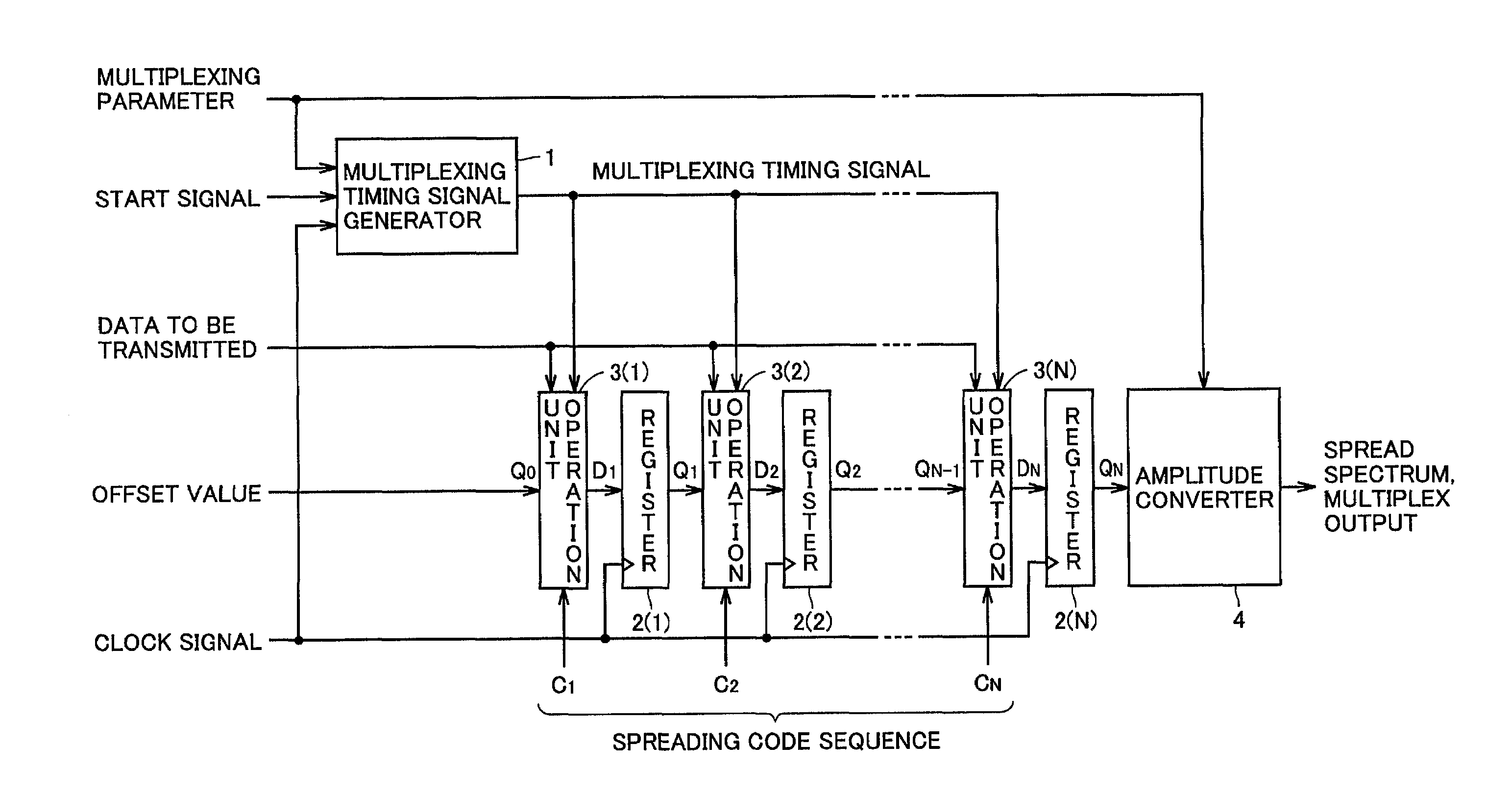
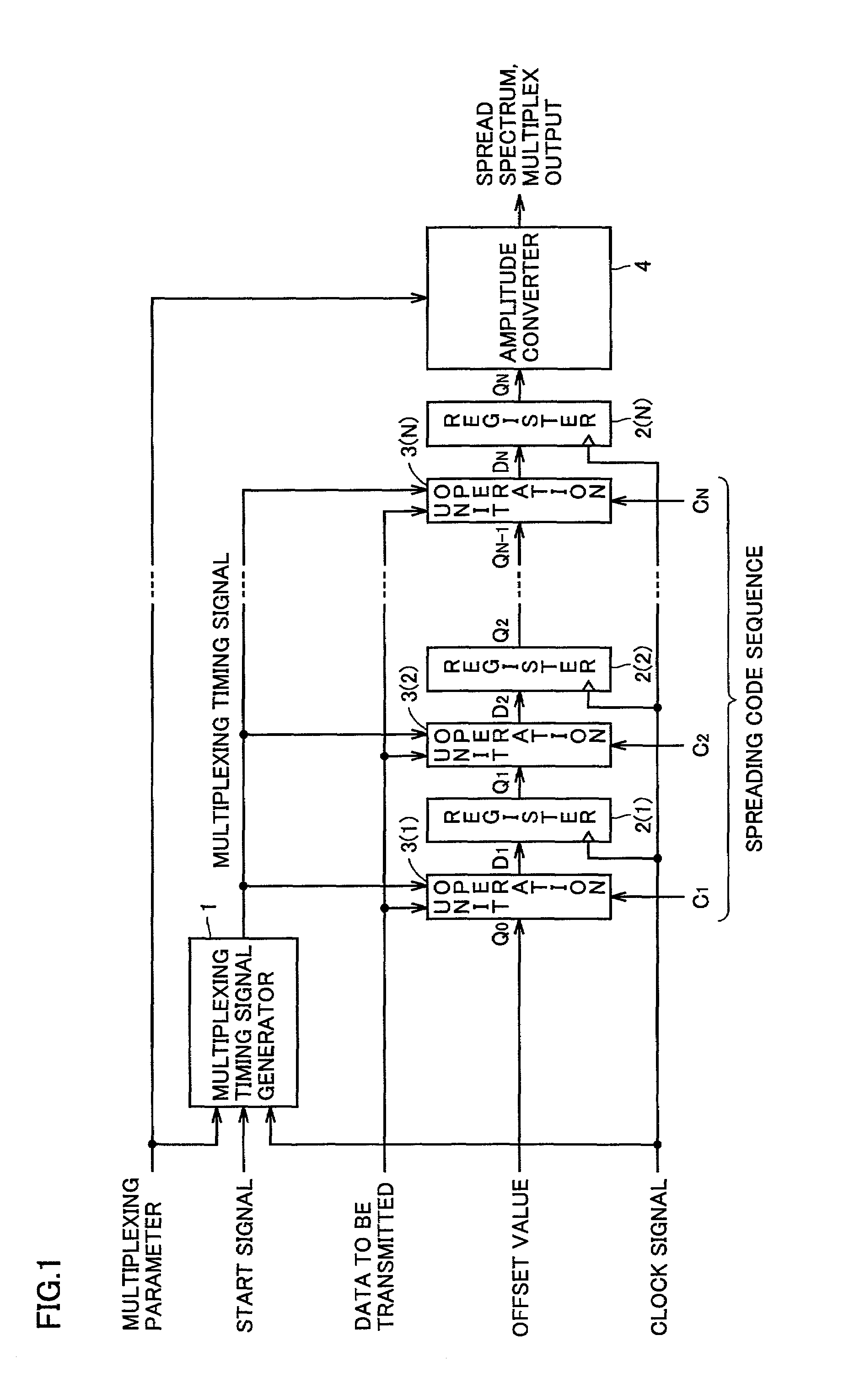
[0059]FIG. 1 is a block diagram illustrating a spreading and multiplexing circuit in a spread spectrum communication transmitter of the present invention.

[0060]In FIG. 1 the spreading and multiplexing circuit includes a multiplexing timing signal generator 1, registers 2(1)–2(N), operation units 3(1)–3(N), and an amplitude converter 4. Multiplexing timing signal generator 1 starts, as timed by a start signal, and is synchronized with a clock signal having a period equal to a chip rate of the spreading, to generate and output a multiplexing timing signal indicating a timing of effecting a multiplexing process. The multiplexing timing signal is generated from a multiplexing parameter representing one or both of information of a selected number of signals in multiplexing and information of a selected pattern of a timing of the multiplexing. N registers 2(1)–2(N) each hold a result of a spreading and multiplexing operation obtain at each chip location, wherein N represents a length of a...


PUM


Abstract

A multiplexing timing signal generator (1) generates a multiplexing timing signal activated for each interval corresponding to a number of chips delayed in multiplexing between data to be transmitted. Driven by the multiplexing timing being active, each operation unit multiplies identical data to be transmitted by a chip of a spreading code sequence and each chip corresponding to a spread spectrum result is added in an operation unit 3(1) to an offset value and in operation units 3(2)–3(N) to their respective, immediately preceding registers 2(1)–2(N−1) values and output as signals for subsequent registers 2(1)–2(N). Thus a multiplexing process is effected. Data to be transmitted has its spectrum spread by a spreading code sequence C1–CN and a result of multiplexing the same in response to a multiplexing timing signal is output from a register(2(N)) by 1 chip at a time in synchronization with a clock signal.

Description

TECHNICAL FIELD[0001]The present invention relates generally to spread spectrum communication transmitters and particularly to a spectrum spreading and multiplexing circuit provided in a spread spectrum communications system at a transmitting modulator to provide a spectrum spreading and multiplexing process by applying a single spreading code sequence to all data to be transmitted to provide spread spectrum data which are in turn delayed by different times, respectively, and a multitude of such delayed, spread spectrum data are added together for each chip corresponding to a minimal unit of the spreading process, to multiplex the data to allow rapid communication.BACKGROUND ART[0002]A spread spectrum communication system is represented by the following equation:[0003]s⁡(t)=∑i=1M⁢⁢(ai⁡(t-τi)-c⁡(t-τi))wherein[0004]s (t): spread-spectrum and multiplexed signal to be transmitted,[0005]ai (t): data to be transmitted having been serial-parallel converted by a number of signals in multipl...

Claims


Application Information

Patent Timeline
Patent Type & Authority Patents(United States)
IPC IPC(8): H04J11/00H04B1/707H04J13/00
CPCH04B1/707H04J13/00H04J13/0077
Inventor ONODERA, TAKASHI
Owner SHARP KK
Why Eureka
Try Eureka