Cross over valve

a cross-over valve and valve body technology, applied in the field of valves, can solve the problems of expensive and bulky equipment attached to each compartment, and achieve the effect of convenient use and convenient us

Inactive Publication Date: 2006-04-11
WASS LLOYD G +1
View PDF11 Cites 9 Cited by
  • Summary
  • Abstract
  • Description
  • Claims
  • Application Information

AI Technical Summary

Benefits of technology

[0007]The present invention is an improved valve assembly called a cross over valve assembly capable of controlled inflation of each compartment in an inflatable device coupled with a safety feature prohibiting deflation of all compartments when only one has a hole causing deflation thereof.

Problems solved by technology

This requires expensive, bulky equipment attached to each compartment.

Method used


Image

  • Cross over valve
  • Cross over valve
  • Cross over valve

Examples


Embodiment Construction

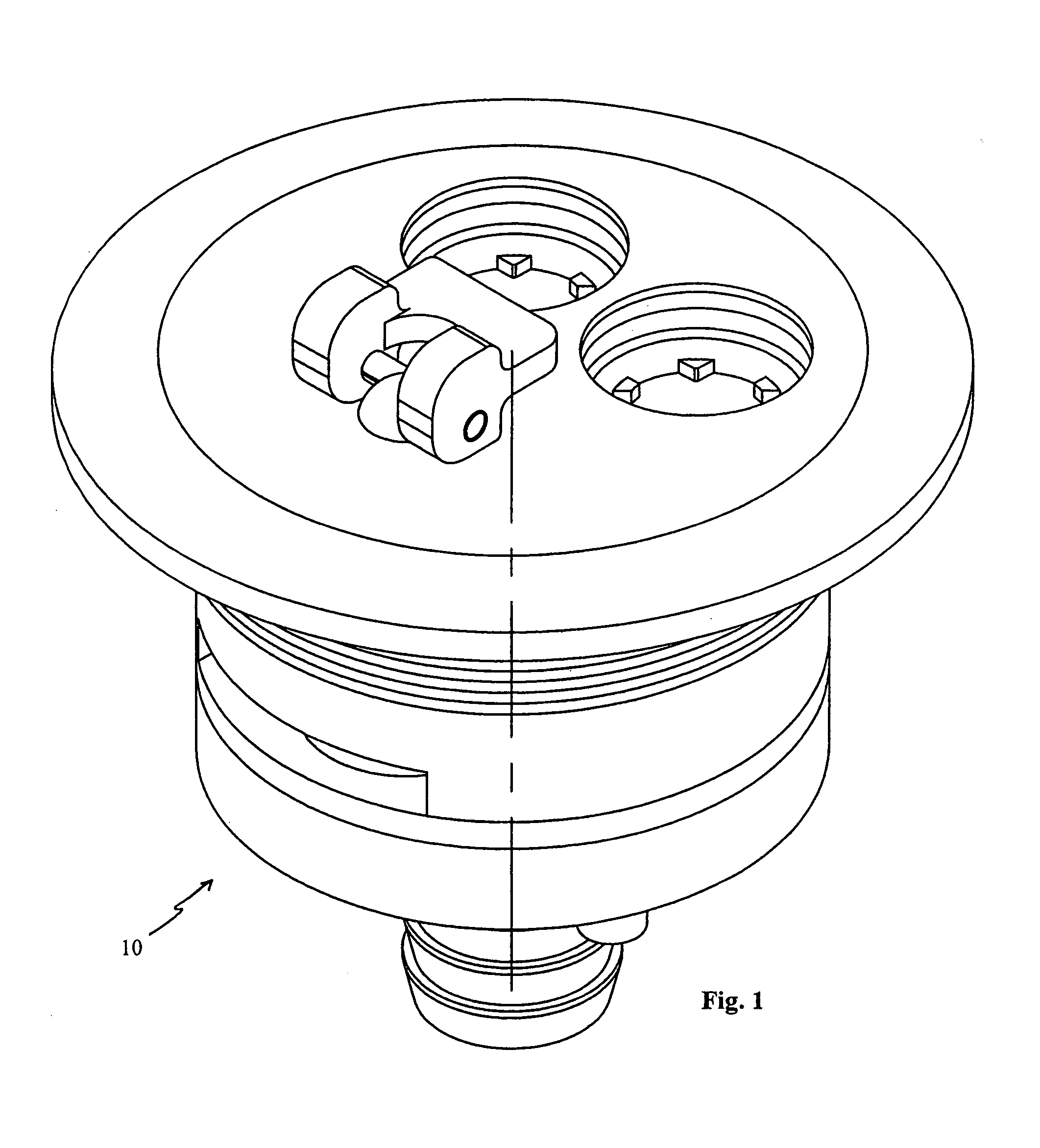
[0040]The cross over valve assembly 10 for use in inflation devices such as life rafts, escape slides, white water rafts, kayaks, and the like is shown in the Figures. This cross over valve assembly 10 is adhered to the inflatable device via adhesive, glue, ultrasonic welding, mechanical clamp, or other methods known by one of skill in the art, where the inflatable device includes a plurality of compartments or chambers, such as for example a first compartment and a second compartment, each separated by a wall or bulkhead. Each of the raft sections or compartments includes an access port.

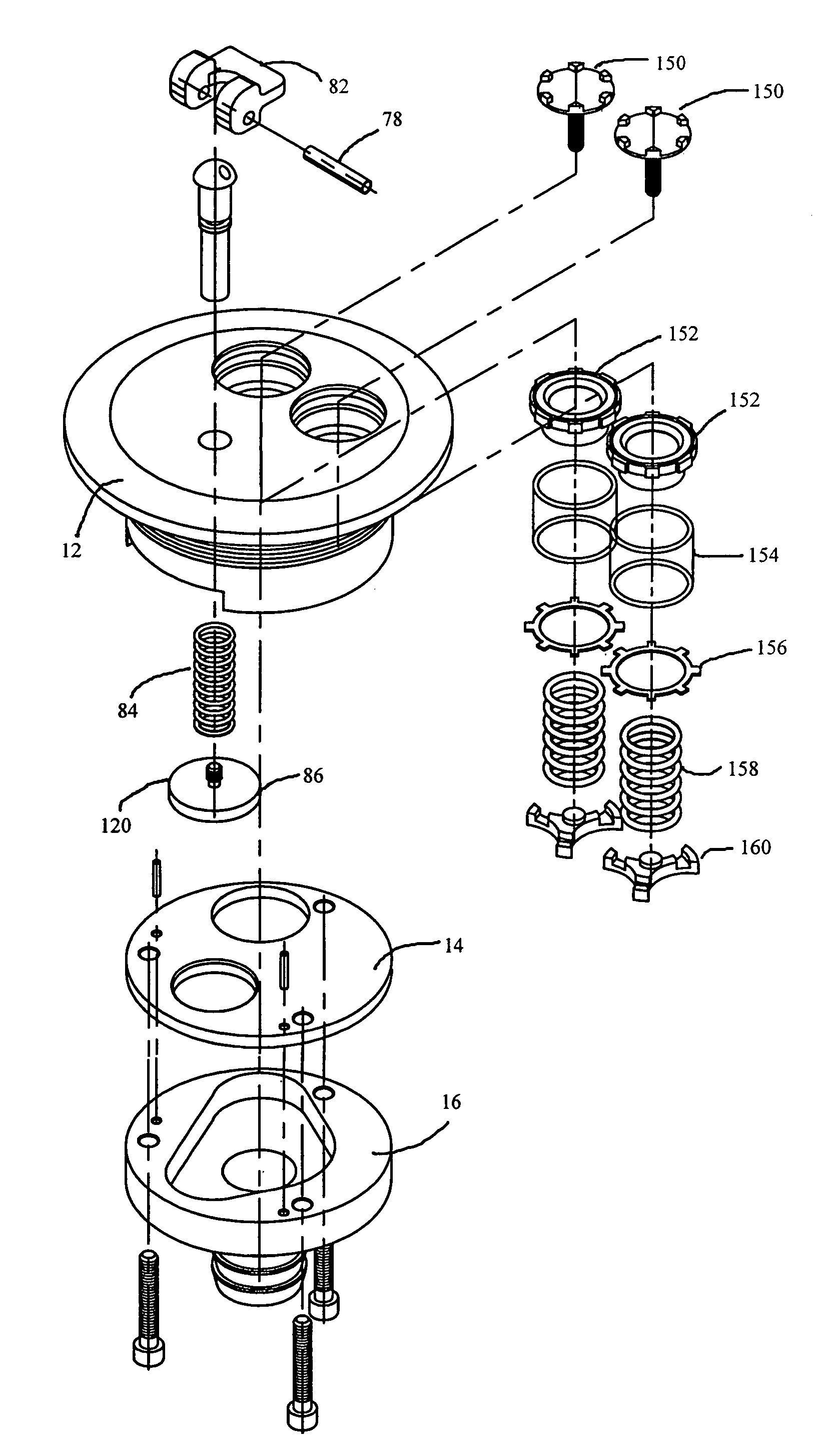
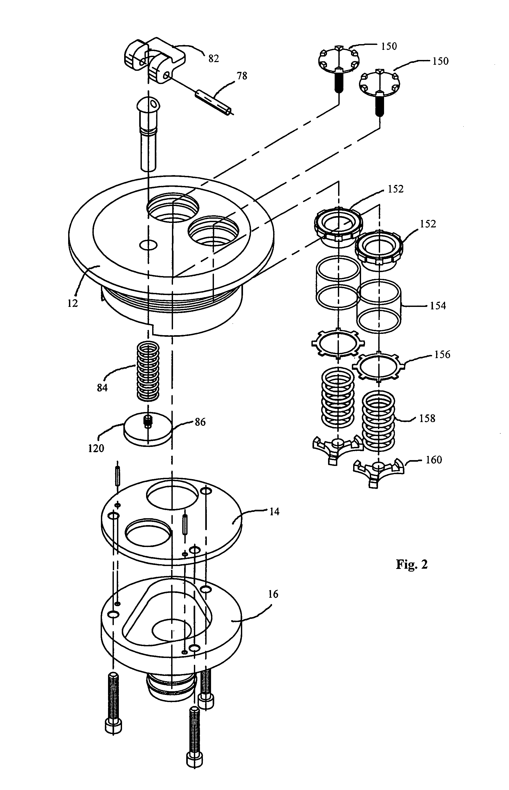
[0041]This improved cross over valve assembly 10 includes a valve body or top plate 12, an intermediate or center plate 14, a bottom plate 16, an intercommunicating valve 18, and a pair of hybrid topping and pressure relief valves 20 and 22.

[0042]Top plate 12 is best shown in FIGS. 3–7 where its general construction is that of a cylindrical body 30 with a flange-like head 32 at one end thereof. The ...


PUM


Abstract

An improved cross over valve for use in conjunction with inflatable devices such as life rafts, escape slides, white water rafts, kayaks, etc. The invention is specifically a cross over valve for inflatable rafts and the like where the valve fluidly connects at least two separate compartments in the inflatable device thereby allowing inflation of the multiple compartments while also providing control of fluid flow therebetween.

Description

[0001]This application claims benefit of Provisional Application Ser. No. 60 / 337,770 filed Nov. 13, 2001.BACKGROUND OF THE INVENTION[0002]1. Technical Field[0003]The invention relates to valves for inflatable device such life rafts, escape slides, white water rafts, kayaks, etc. and more particularly a cross over valve for inflatable rafts and the like where the valve fluidly connects at least two separate compartments in the inflatable device thereby allowing inflation of the multiple compartments while also providing control of fluid flow therebetween.[0004]2. Background Information[0005]For years, numerous different types of inflatable devices have been used for a variety of reasons. For instance, inflatable life rafts have been regularly provided on large aircrafts and water vessels for decades including those used by the military. These inflatable life rafts provide the necessary flotation vessels as would be needed by the passengers of the aircraft or water vessel should the a...

Claims


Application Information

Patent Timeline
Patent Type & Authority Patents(United States)
IPC IPC(8): F16K15/20B63B35/58F16K11/10
CPCF16K15/20F16K11/10Y10T137/3584Y10T137/87249
Inventor WASS, LLOYD G.VENNE, ROBERT
Owner WASS LLOYD G
Why Eureka
Try Eureka