Sheet pile for forming barrier walls

a technology of sheet piles and barrier walls, applied in the direction of shaft equipment, shaft linings, shafts, etc., can solve the problems of increased pile costs, increased bending strength, and damage to boats, barges,

Inactive Publication Date: 2006-04-11
CMI CO LTD
View PDF23 Cites 28 Cited by
  • Summary
  • Abstract
  • Description
  • Claims
  • Application Information

AI Technical Summary

Problems solved by technology

The additional material used in over-sizing increases the costs of the piles due to the material itself as well as the costs associated with handling the heavier piles.
The increased bending strength does not offset the cost of the additional plastic.
These obstructions are subject to damage from, and may cause damage to, boats, barges, and like craft that frequently operate near and are secured to such barrier walls.

Method used


Image

  • Sheet pile for forming barrier walls
  • Sheet pile for forming barrier walls
  • Sheet pile for forming barrier walls

Examples


Embodiment Construction

[0017]Reference will now be made in detail to the description of the invention as illustrated in the drawings. While the invention will be described in connection with these drawings, there is no intent to limit it to the embodiment or embodiments disclosed therein. On the contrary, the intent is to cover all alternatives, modifications and equivalents included within the spirit and scope of the invention as defined by the appended claims.

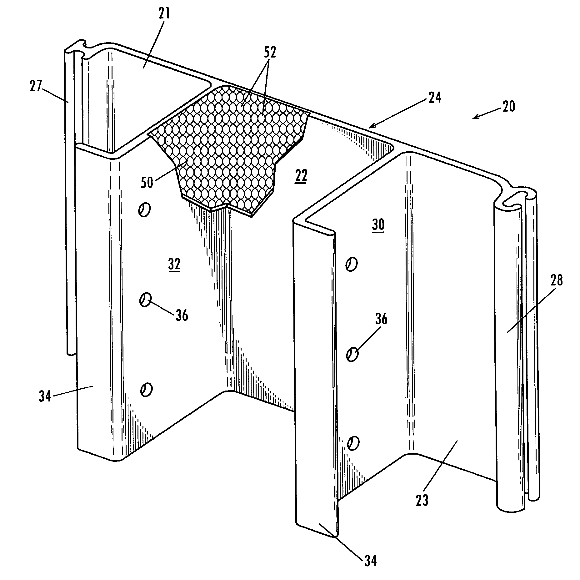
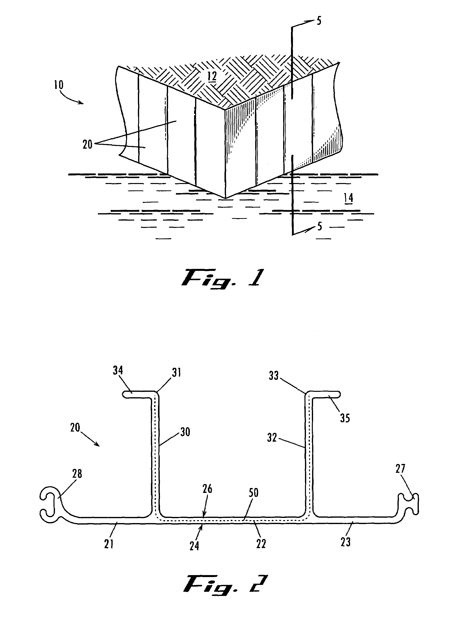
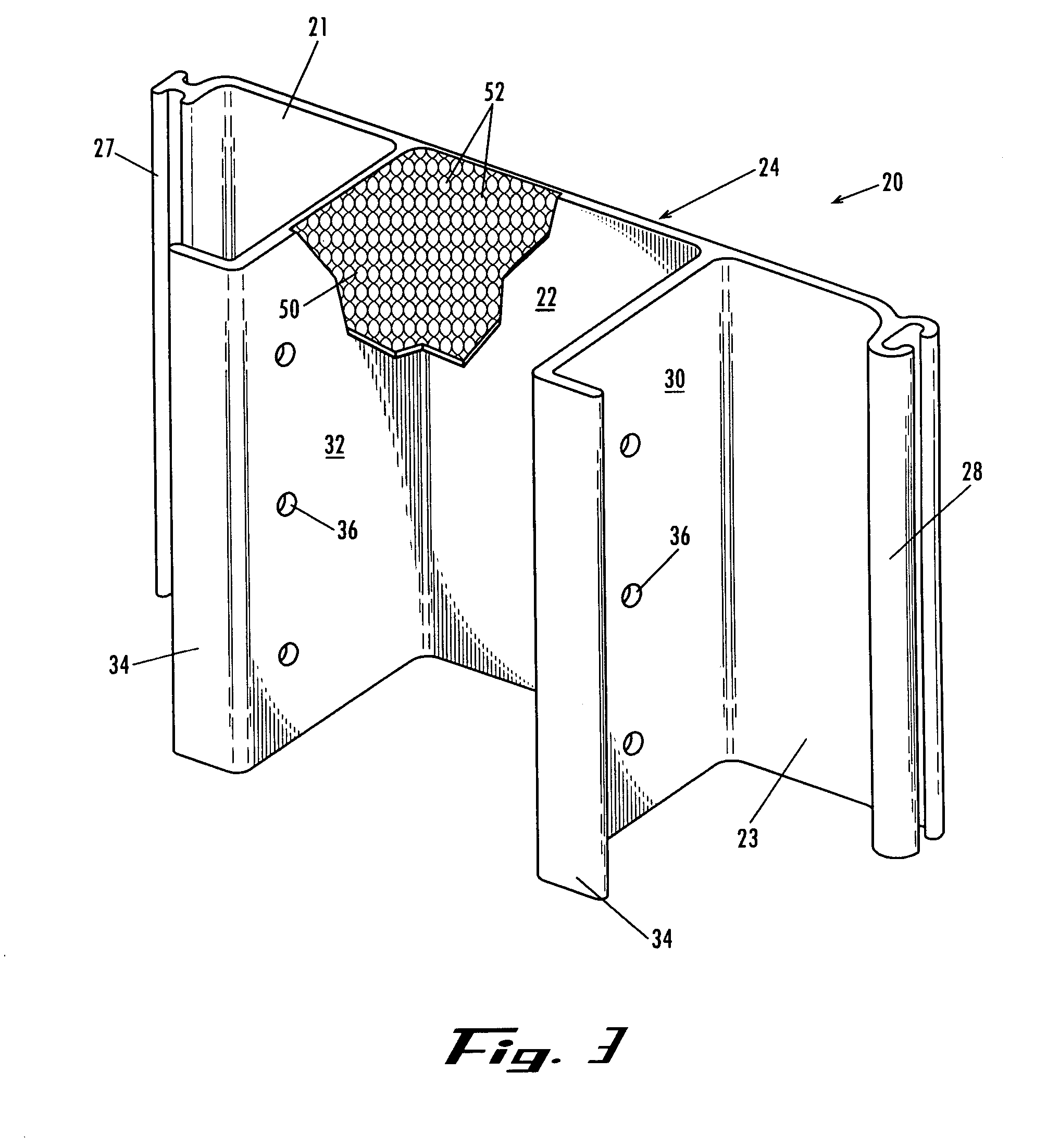
[0018]In particular, FIG. 1 illustrates a barrier wall, in the form of a sea wall 10, constructed of structural panels 20 according to the present invention. Typically, the sea wall 10 forms a retainer for the soil 12 on the backside of the structural panels 20, with water 14 at the front surface. The panels 20, as shown in FIGS. 5A and 5B, extend vertically with lower ends received in the subsoil below the lower level of the body of water 14. The panels 20 are joined in side edge to side edge relation and maintained in the desired position by an a...


PUM


Abstract

A series of duplicate structural panels form a substantially flat sea wall, barrier wall, and the like, fabricated of synthetic resin material for driving into soils. The structural panel is elongated and of constant size and shape along its length, and is characterized by having been extruded lengthwise. The structural panel includes, in cross section, a central wall section having an inner surface, an outer surface, and opposed side wall sections. A male locking element is disposed on and extends laterally from one side section and a female locking element is disposed on and extends laterally from the other side wall section, the female locking element being configured to slidably receive and retain the male locking element. First and a second strengthening flanges are integrally formed on the inner surface, both substantially perpendicular to the central wall section and substantially parallel to each other. The first and second strengthening flanges extend along the length of the structural panel.

Description

FIELD OF THE INVENTION[0001]The present invention relates generally to extruded structural panels fabricated of synthetic materials that are useful as pilings for driving into the earth and for forming sea walls, piers, dikes, barrier walls, retaining walls and the like. More specifically, the present invention relates to a structural panel constructed so as to minimize deterioration of the structural panel due to exposure to the elements and allow construction of a barrier wall having an exposed outer surface that is substantially free of protrusions and / or obstructions.BACKGROUND OF THE INVENTION[0002]Barrier walls that are formed from a plurality of elongated, vertically oriented piles typically are driven into the earth to a depth sufficient to support the panels in an upright attitude. In some cases, the piles are in the form of extruded structural panels and are formed with male and female opposed edges so that similar panels can be locked together at their adjacent side edges...

Claims


Application Information

Patent Timeline
Patent Type & Authority Patents(United States)
IPC IPC(8): E02D5/02E02D5/08E02D5/16E02D5/03E02D29/02
CPCE02D29/0241E02D5/03
Inventor IRVINE, JOHN E.
Owner CMI CO LTD
Why Eureka
Try Eureka