Apparatus for connecting and organizing cords and cables

a technology for connecting and organizing cables and accessories, applied in the field of compact devices, can solve the problems of haphazard, confusing, unsightly, unsafe, etc., and achieve the effects of avoiding the rat's nest of wiring and accessory devices, avoiding the rat's nest of wiring and accessories, and avoiding the use of cords and cables

Inactive Publication Date: 2006-04-11
LEAP TECH
View PDF18 Cites 62 Cited by
  • Summary
  • Abstract
  • Description
  • Claims
  • Application Information

AI Technical Summary

Benefits of technology

[0009]Accordingly there is disclosed herein an apparatus for concealing, connecting and organizing power cords and signal cables from multiple devices in an equipment installation. The apparatus includes a compact enclosure for use on a desktop that has first and second interior side panels facing each other without obstruction therebetween across a floor of the enclosure, at least one front or rear access opening, and a hinged, reinforced, load-bearing top lid. A plurality of AC power outlets is disposed on either or both of the first and second interior side panels and connected in a power circuit via an ON / OFF switch to a power supply cord. Electrical circuitry is coupled with the power circuit for suppressing interference and transients, and providing protection against excessive current being drawn from the unit. The enclosure of the apparatus includes space for containing and plugging in compact power supply blocks and storage space between the first and second interior panels for connecting, organizing and storing excess lengths of the cords and cables.

Problems solved by technology

The management of cords, cables and accessory devices in multiple unit installations of audio, video, computing, security or maintenance equipment is an ongoing problem because of the variety of devices that may be connected together in a system, where each device typically includes a separate power cord and may require one or more signal cables or other connecting cables or interfaces in the system.
If the system includes more than two or three items of equipment, the organizing, concealing and storage of the cords and cables becomes more difficult, often resulting in haphazard, confusing, unsightly and even unsafe “rat's nests” of wiring and accessory devices.
Even though conventional outlet strips can be used to provide an electrical outlet or receptacle for each power cord in the system, this solution does not otherwise address the problem of organizing, concealing or managing an assortment of many cords.
Further, many devices require the use of numerous signal cables for conveying signals into and out of the device.
Such cables, if organized at all, are most often bundled together with a cable tie, a piece of tape or a cord; yet this typical solution often does not adequately address the problem of organizing, concealing or otherwise managing an assortment of numerous cables.
However, the internal structures to support such loads also provide some obstruction to the placement or arrangement of cords within the housing, thereby limiting the use of the interior space for storage.
Further, it is a very low profile design that precludes the storage therein of power supply blocks such as typically used to supply power for printers, modems and other peripherals or accessories.
Without such internal structures within the storage space of this housing, the load-bearing capacity of the housing is diminished.
However, the solution disclosed in this patent suffers from the same deficiencies as the one preceding in that the posts and covering means for securing the cords that occupy some of the storage space obstructs the storage space, limiting the use that may be made of it for storing cords or cables or other items.
In addition, this unit lacks any power line filtering or transient suppression.
However, this unit, while it has ample storage space for cords and cables, is not suitable for desktop or component shelf use because of its bulk.
However, this basket is not capable of concealing the cords stored within it.
Further, it appears to be unsuited to use on a desktop or component shelf.

Method used


Image

  • Apparatus for connecting and organizing cords and cables
  • Apparatus for connecting and organizing cords and cables
  • Apparatus for connecting and organizing cords and cables

Examples


Embodiment Construction

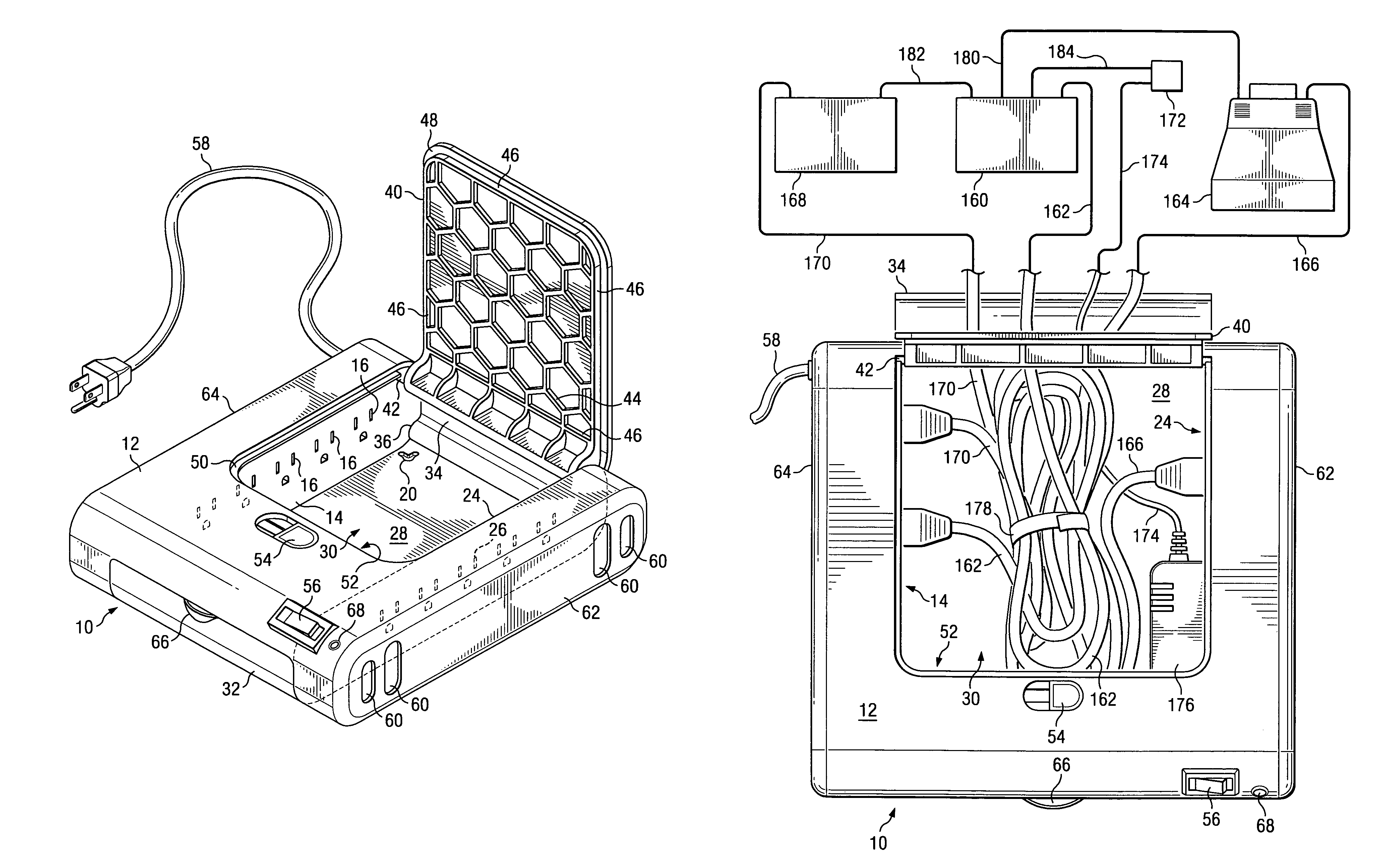
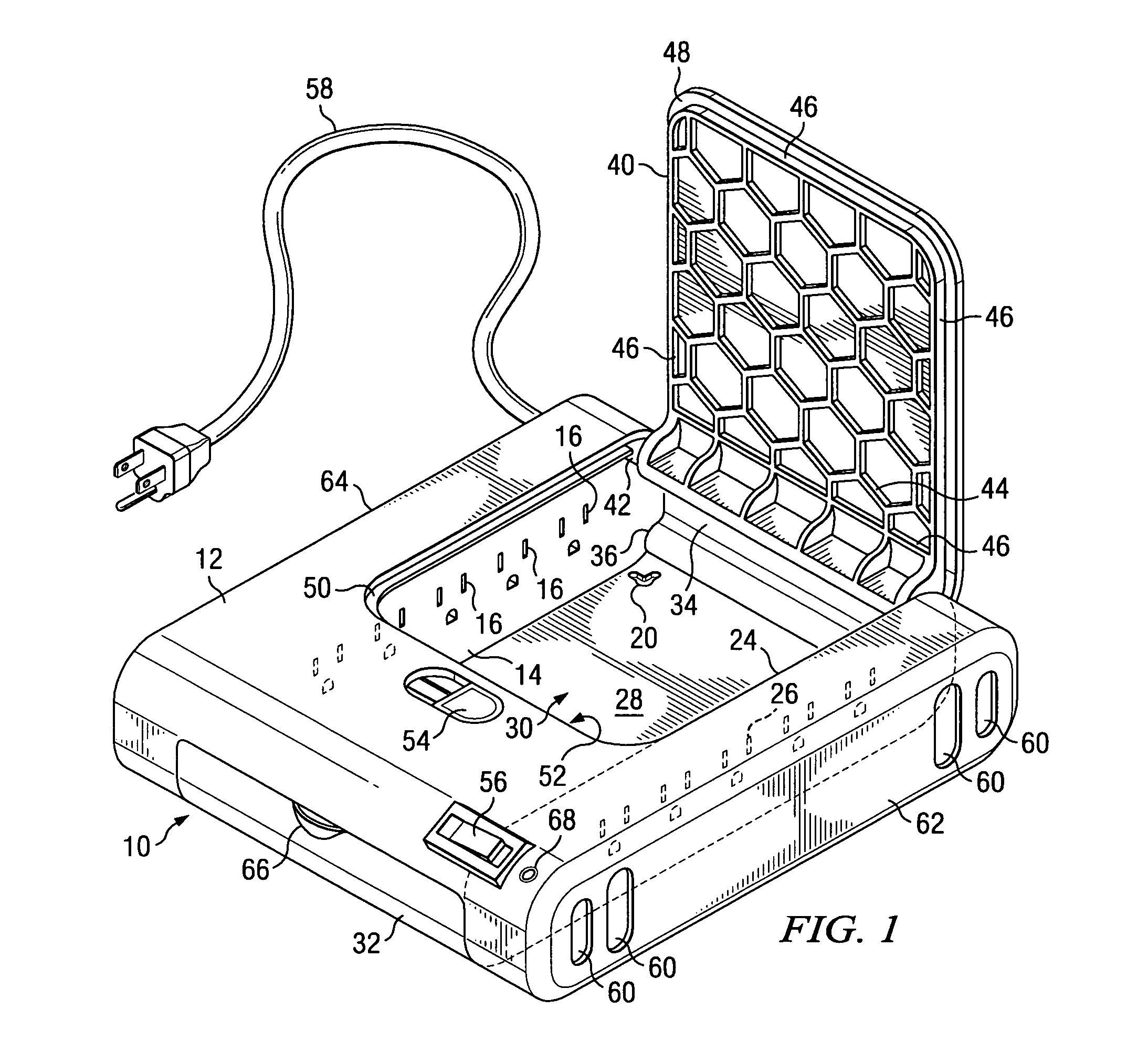
[0022]FIG. 1 illustrates a perspective view of one embodiment of a device for connecting and storing or concealing cords and cables according to the present disclosure. The device, for purposes of the present description, will be called a connection system 10. The connection system 10 may be used for connecting and storing or concealing the power cords and / or low voltage power supply “blocks” from multiple components in an equipment installation. The equipment installation may include components of an audio system, a video system, a computing system, a security system, a maintenance system and the like. The connection system 10 may also be used, for example, as a data network hub containing expansion or connectivity modules and their associated signal and power cables or cords. The illustrative embodiment of the connection system 10 described herein is approximately 12″×12″×2-¾″ and is compact enough to be placed on a component shelf or desktop. It may also be mounted on a wall of a...


PUM


Abstract

There is disclosed an apparatus for concealing, connecting and organizing power cords and signal cables from multiple devices in an equipment installation comprising a compact enclosure for use on a desktop that has first and second interior side panels facing each other without obstruction across the floor of the enclosure, and a hinged, reinforced, load-bearing top lid. A plurality of AC power outlets is disposed on either or both of the first and second interior side panels and connected in a power circuit via an ON / OFF switch to a power supply cord. The power circuit includes circuits for suppressing interference and transients. The enclosure includes space for containing and plugging in compact power supply blocks and storage space between the first and second interior panels for connecting, organizing and storing excess lengths of the cords and cables.

Description

CROSS REFERENCE TO RELATED APPLICATIONS[0001]The present application claims priority to a U.S. Provisional Patent Application Ser. No. 60 / 539,390 filed Jan. 27, 2004 and entitled “Device to Secure And Protect Communications Cables And Power Cords;” and is related to U.S. Design patent application Ser. No. 29 / 211,543 filed Aug. 18, 2004 and entitled “Enclosure For Desktop Power Cord And Cable Management.”FIELD OF THE INVENTION[0002]The present invention generally relates to apparatus and methods for managing cords, cables and accessories in equipment installations and, more particularly, to compact, desktop-sized apparatus for connecting, organizing and storing cords, cables and accessories in multiple unit equipment installations.BACKGROUND AND DESCRIPTION OF THE PRIOR ART[0003]The management of cords, cables and accessory devices in multiple unit installations of audio, video, computing, security or maintenance equipment is an ongoing problem because of the variety of devices that ...

Claims


Application Information

Patent Timeline
Patent Type & Authority Patents(United States)
IPC IPC(8): H01R13/72H01R25/00
CPCH01R25/003H01R13/72
Inventor ROSENTHAL, LESLIE DAVIDHOLLAND, JASON SCOTT
Owner LEAP TECH
Why Eureka
Try Eureka