Belt sander having sand belt replacement apparatus

a belt sander and replacement technology, which is applied in the field of belt sanders, can solve the problems of user inconvenience when mounting and replacing the sand belt, and the danger of the user during the operation of the belt sander, and achieve the effect of easy and rapid mounting and replacement of the sand bel

Inactive Publication Date: 2006-04-11
MAO SHAN MACHINERY INDAL
View PDF8 Cites 7 Cited by
  • Summary
  • Abstract
  • Description
  • Claims
  • Application Information

AI Technical Summary

Benefits of technology

[0006]The primary objective of the present invention is to provide a belt sander having a s

Problems solved by technology

However, the user's one hand has to press the operation lever 2 and his other hand has to remove the worn sand belt and replace a new sand belt, thereby causing inconvenience to the user when mounting and replacing the

Method used


Image

  • Belt sander having sand belt replacement apparatus
  • Belt sander having sand belt replacement apparatus
  • Belt sander having sand belt replacement apparatus

Examples


Embodiment Construction

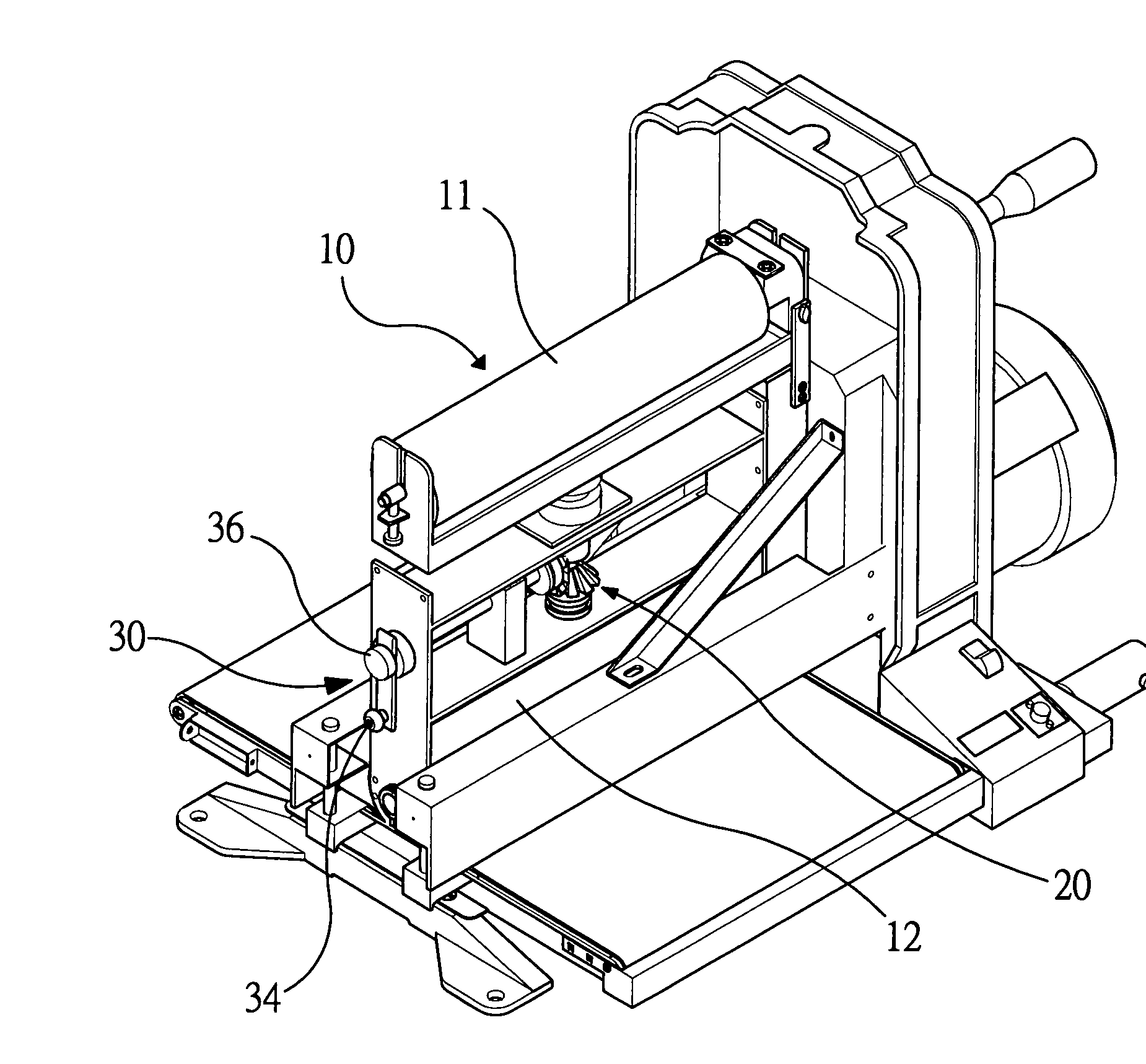
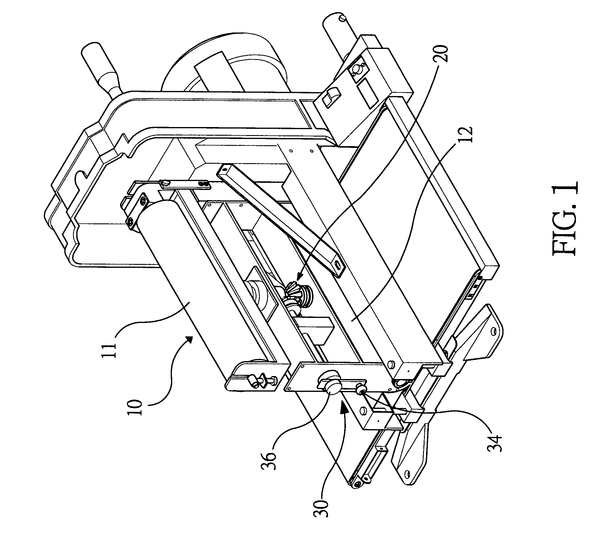
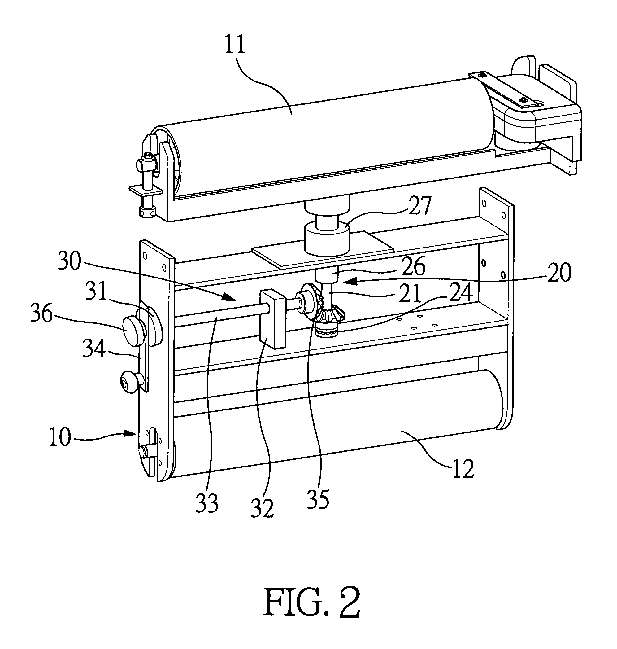
[0021]Referring to the drawings and initially to FIGS. 1–6, a belt sander in accordance with the preferred embodiment of the present invention comprises a main frame 10, a drive roller 12 rotatably mounted on the main frame 10, a driven roller 11 rotatably mounted on the main frame 10, a sand belt (not shown) mounted between the drive roller 12 and the driven roller 11, and a sand belt replacement apparatus mounted on the main frame 10 for driving the driven roller 11 to move relative to the drive roller 12 so as to adjust a distance between the drive roller 12 and the driven roller 11 to facilitate a user replacing the sand belt.

[0022]The sand belt replacement apparatus includes a lifting mechanism 20 and an adjusting mechanism 30.

[0023]The lifting mechanism 20 includes a lifting rod 26 movably mounted on the main frame 10 and having a hollow lower end formed with an inner thread 260 (see FIG. 6) and an upper end connected to the driven roller 11 to drive the driven roller 11 to mo...


PUM


Abstract

A belt sander includes a main frame, a drive roller, a driven roller, a sand belt, and a sand belt replacement apparatus. Thus, the user only needs to rotate the control handle to move the driven roller relative to the drive roller so as to change the distance between the drive roller and the driven roller so that the user can adjust the tension of the sand belt easily and rapidly, thereby facilitating the user adjusting the tension of the sand belt, and thereby facilitating the user mounting and replacing the sand belt.

Description

BACKGROUND OF THE INVENTION[0001]1. Field of the Invention[0002]The present invention relates to a belt sander, and more particularly to a belt sander having a sand belt replacement apparatus.[0003]2. Description of the Related Art[0004]A conventional belt sander in accordance with the prior art shown in FIG. 10 is disclosed in the applicant's U.S. Pat. No. 6,769,974-B2 and comprises a drive roller 3, a driven roller 4, a tension spring 1, and an operation lever 2. When the sand belt mounted between the drive roller 3 and the driven roller 4 is worn out for replacement, the operation lever 2 is pressed downward to compress the tension spring 1 to loosen the sand belt mounted between the drive roller 3 and the driven roller 4, thereby facilitating the user removing the sand belt.[0005]However, the user's one hand has to press the operation lever 2 and his other hand has to remove the worn sand belt and replace a new sand belt, thereby causing inconvenience to the user when mounting a...

Claims


Application Information

Patent Timeline
IPC IPC(8): B24B21/00
CPCB24B21/20
Inventor WANG, TIEN-WANG
Owner MAO SHAN MACHINERY INDAL
Why Eureka
Try Eureka