Eureka AIR delivers breakthrough ideas for toughest innovation challenges, trusted by R&D personnel around the world.

Cymbal support structure

a support structure and cymbal technology, applied in the direction of instruments, percussion instruments, instruments, etc., can solve the problems of laborious and time-consuming replacement of the cymbal, easy wear and loosening of the screw nut b>4/b>, etc., to achieve easy and rapid replacement of the cymbal, and easy rotation of the rotary element to assemble and disassemble the

Active Publication Date: 2012-09-20
LIAO TSUN CHI
View PDF1 Cites 2 Cited by
  • Summary
  • Abstract
  • Description
  • Claims
  • Application Information

AI Technical Summary

Benefits of technology

[0004]The primary objective of the present invention is to provide a cymbal support structure, whereby the user can easily and rapidly to replace the cymbal.
[0005]To achieve the abovementioned objective, the present invention proposes a cymbal support structure for holding a cymbal. The cymbal support structure comprises a rod, a nut, a rotary element, an upper felt, a lower felt, a compression element, and an elevation adjustment ring. The rotary element and the nut are respectively formed in an elongate shape. The nut is fastened to one end of the rod. The rotary element is pivotally coupled to the nut. The upper and lower felts clamp the cymbal. When the rotary element is rotated to parallel the nut, the cymbal, the upper felt and the lower felt can pass through the nut and the rotary element to couple on the rod. When the rotary element is rotated to not parallel the nut, the cymbal, the upper felt and the lower felt can be prevented from passing through the rod. The compression element is coupled on the rod. The elevation adjustment ring is screwed on the rod to push the compression element to compress the lower felt upwards.
[0006]In the present invention, the user can easily rotate the rotary element to assemble and disassemble the cymbal to rapidly replace the cymbal. Further, the rotary element also can effectively secure the cymbal without being loosened during percussion. Furthermore, the elevation adjustment ring can be moved along the rod to adjust the height thereof and alter the compression degree of the compression element, whereby the cymbal can generate different resonant sounds to meet user's requirements.

Problems solved by technology

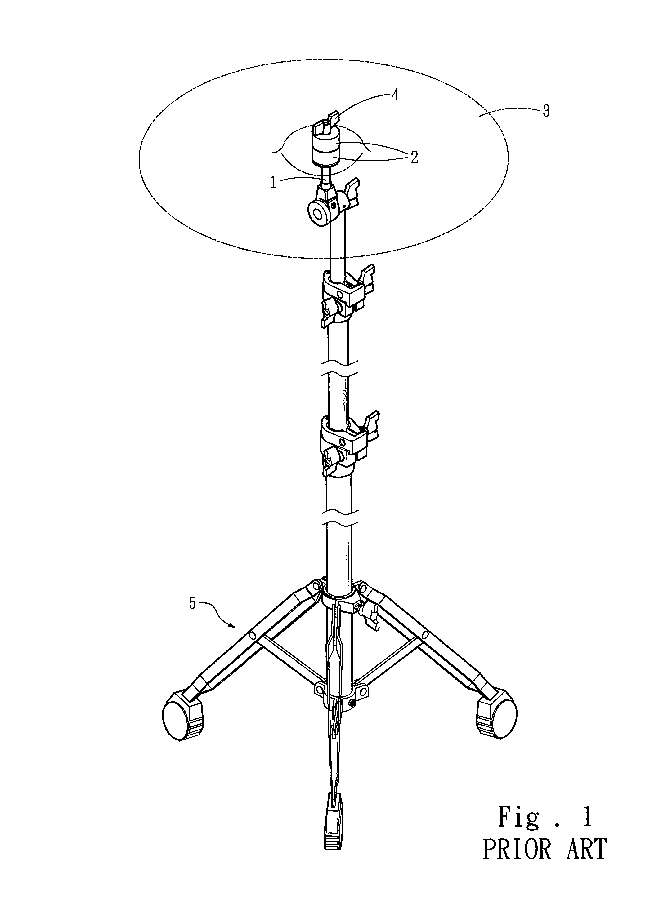
Therefore, replacing the cymbal 3 is laborious and time-consuming.
Further, the screw nut 4 is likely to be worn and loosened after it has been mounted and dismounted repeatedly.

Method used


Image

  • Cymbal support structure
  • Cymbal support structure
  • Cymbal support structure

Examples


Embodiment Construction

[0014]Below, the embodiments are described in detail in cooperation with the drawings to demonstrate the technical contents, characteristics and efficacies of the present invention.

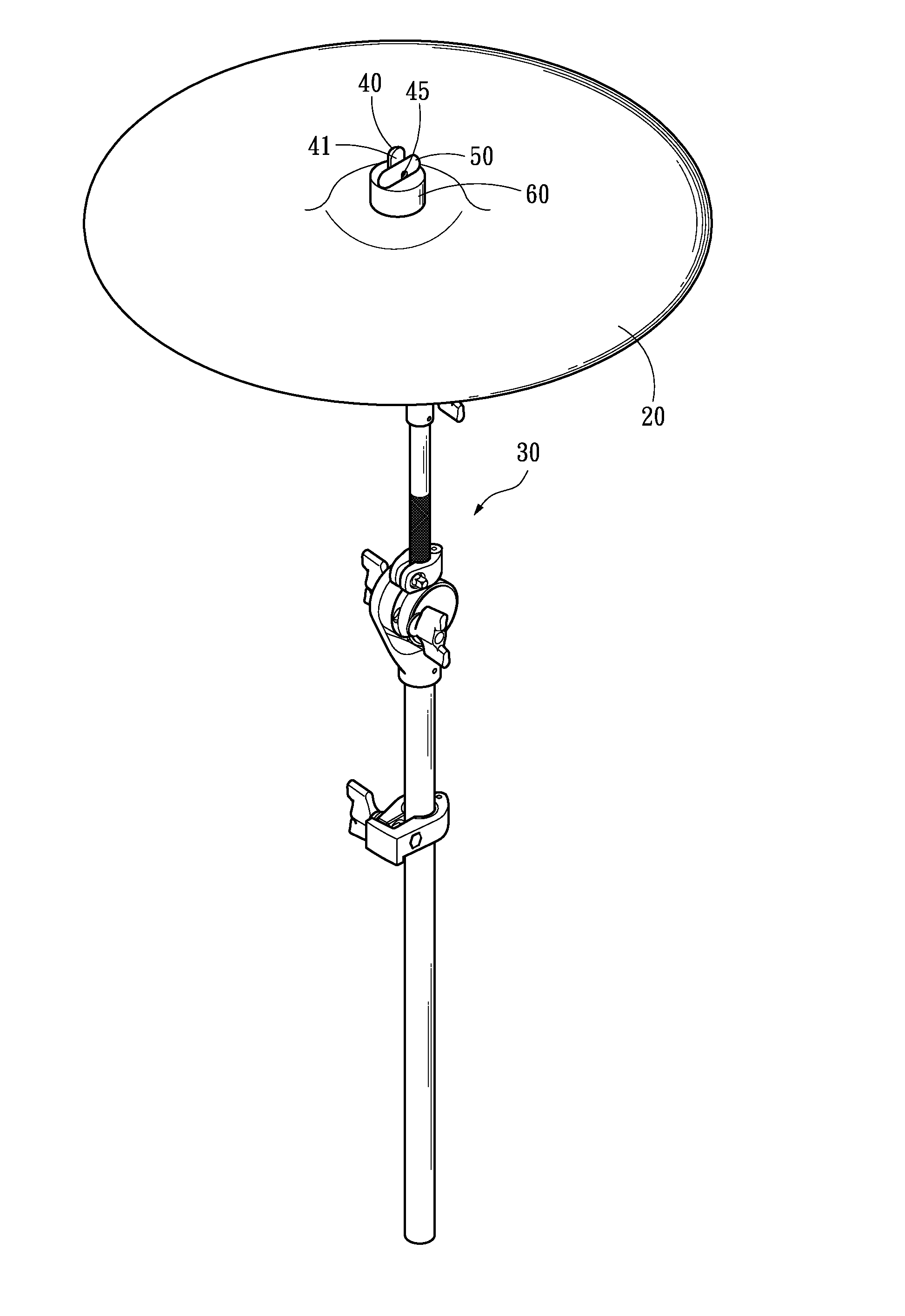
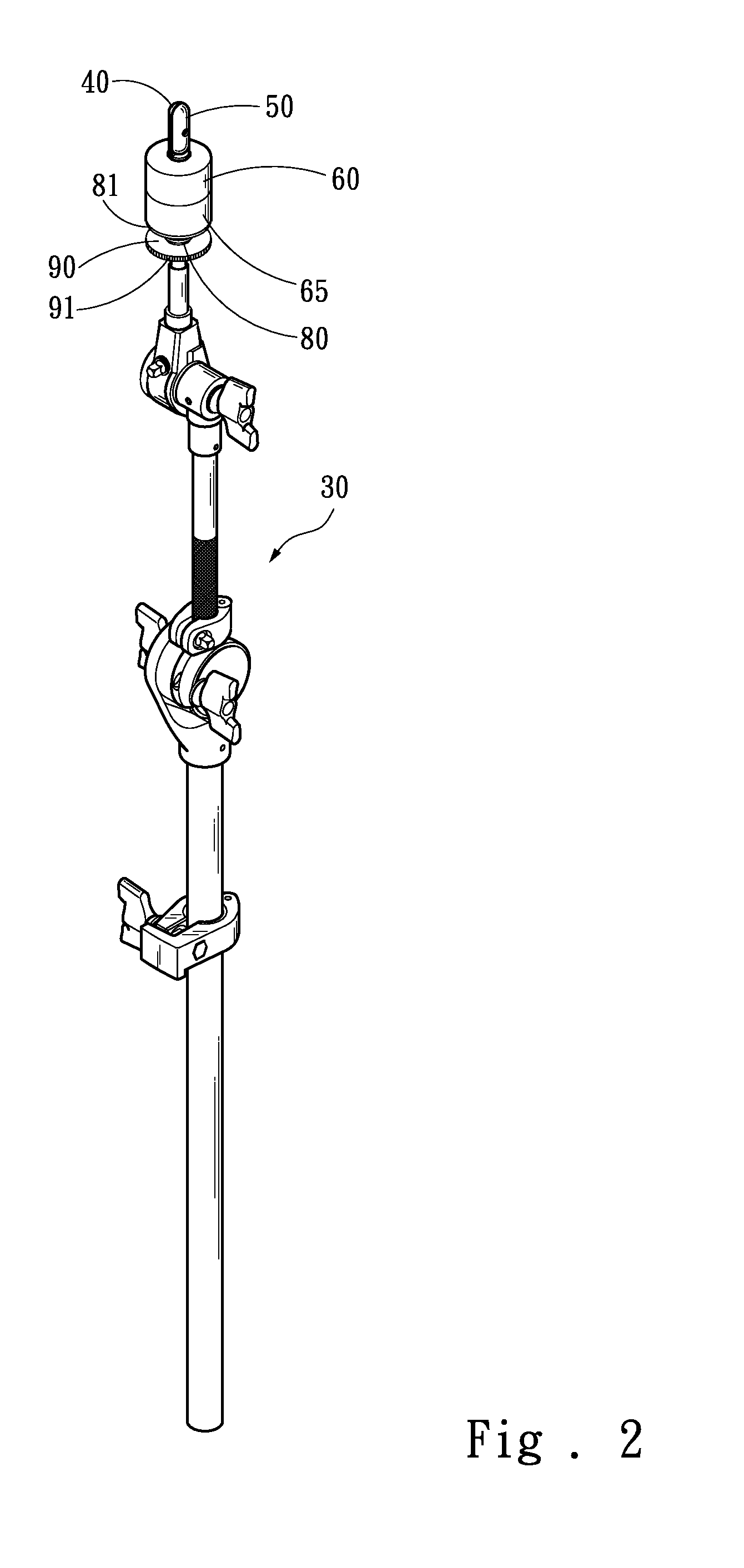
[0015]Refer to FIG. 2, FIG. 3 and FIG. 4. The present invention proposes a cymbal support structure for holding a cymbal 20. The cymbal support structure comprises a rod 30, a nut 40, a rotary element 50, a screw 45, an upper felt 60, a lower felt 65, a plastic sleeve 70, a compression element 80, and an elevation adjustment ring 90. The rotary element 50 and the nut 40 are respectively formed in an elongate shape. The nut 40 is fastened to one end of the rod 30. The rod 30 has threads 31, and the nut 40 is screwed on a distal end of the threads 31.

[0016]The screw 45 is inserted into the middle portion of the rotary element 50 and screwed onto the nut 40. Thereby, the rotary element 50 is pivotally coupled to the nut 40. The nut 40 has a notch 41 where the rotary element 50 is pivotally coupled to. When t...


PUM


Abstract

A cymbal support structure for holding a cymbal comprises a rod, a nut, a rotary element, an upper felt, a lower felt, a compression element, and an elevation adjustment ring. The nut is fastened to one end of the rod. The rotary element is pivotally coupled to the nut. The upper and lower felts clamp the cymbal. When the rotary element is rotated to parallel the nut, the cymbal and the upper and lower felts pass through the nut and rotary element to couple on the rod. When the rotary element is rotated to not parallel the nut, the cymbal and the upper and lower felts are prevented from passing through the rod. The elevation adjustment ring is screwed on the rod to push the compression element to compress the lower felt upwards. Via rotating the rotary element, the user can easily assemble or disassemble the cymbal to perform replacement.

Description

FIELD OF THE INVENTION[0001]The present invention relates to a cymbal support structure, particularly to a cymbal support structure for holding a cymbal which can be assembled and disassembled rapidly.BACKGROUND OF THE INVENTION[0002]Refer to FIG. 1. The conventional cymbal support structure comprises a stand 5, a rod 1 installed on the stand 5, two damping felts 2 penetrated by the top of the rod 1, a cymbal 3 clamped by the two felts 2, and a screw nut 4 screwed into the rod 1 to secure the two felts 2, whereby the cymbal 3 is held by the upper and lower felts 2.[0003]The user may percuss the cymbal 3 installed on the abovementioned support structure to generate sounds. However, the cymbal 3 is disassembled after the screw nut 4 has been dismounted 3. Therefore, replacing the cymbal 3 is laborious and time-consuming. Further, the screw nut 4 is likely to be worn and loosened after it has been mounted and dismounted repeatedly. Thus, the screw nut 4 cannot fasten the felts 2 secure...

Claims


Application Information

Patent Timeline
Patent Type & Authority Applications(United States)
IPC IPC(8): G10D13/06G10D13/063
CPCG10D13/06G10D13/28G10D13/063
Inventor LIAO, TSUN-CHI
Owner LIAO TSUN CHI
Why Eureka
Eureka Blog
Learn More