
Contact tube for a welding torch

a technology of contact tube and welding torch, which is applied in the direction of welding media, electric discharge heating, workpiece edge portions, etc., can solve the problems of increased abrasion of welding wire, no readjustment of contact force, and inability to maintain the set contact force, so as to prevent or at least reduce the disadvantages of known contact tubes

Active Publication Date: 2013-10-01
FRONIUS INTERNATIONAL GMBH
View PDF26 Cites 1 Cited by
  • Summary
  • Abstract
  • Description
  • Claims
  • Application Information

AI Technical Summary

Benefits of technology

The present invention provides a contact tube for a welding torch that can ensure consistent and permanent contact with the welding wire over its lifespan. The invention includes one or more slots in the inlet and outlet areas of the contact tube, which allows for mirror-inverted movement of the parts on both sides of the slots, automatically adjusting the contact force and optimizing the contact force for different welding wire diameters. The flexible closure part also ensures minimal abrasion of the welding wire and compensates for the abrasion of the opening in the contact tube. The contact tube is easy to replace and can be adapted to different welding wire diameters. The slots in the outlet area are designed to protect against contaminants and ensure secure contact with the welding wire. The invention also includes a conical inner surface of the ring-shaped expansion for fastening of a conical adapter part, which improves the regulation and transmission of the contact force to the welding wire. The curved inner surface of the ring-shaped expansion further enhances the contact and heat dissipation.

Problems solved by technology

It is disadvantageous in this case that no readjustment of the contact force is possible, and the outlet opening is expanded again by the resulting abrasion of the welding wire in the contact tube and the set contact force thus can no longer be maintained.
It is disadvantageous in this case that the mobility is restricted by the resistance on the fixed body, so that the contact force on the welding wire can only be set to a limited extent and increased abrasion of the welding wire is caused.
Furthermore, the replacement of the contact tube is connected with an increased time expenditure, since additional connections of elements to the contact tube must be detached.

Method used


Image

  • Contact tube for a welding torch
  • Contact tube for a welding torch
  • Contact tube for a welding torch

Examples


Embodiment Construction

[0039]For introductory purposes, it is noted that identical parts of the variants and embodiments are provided with identical reference numerals.

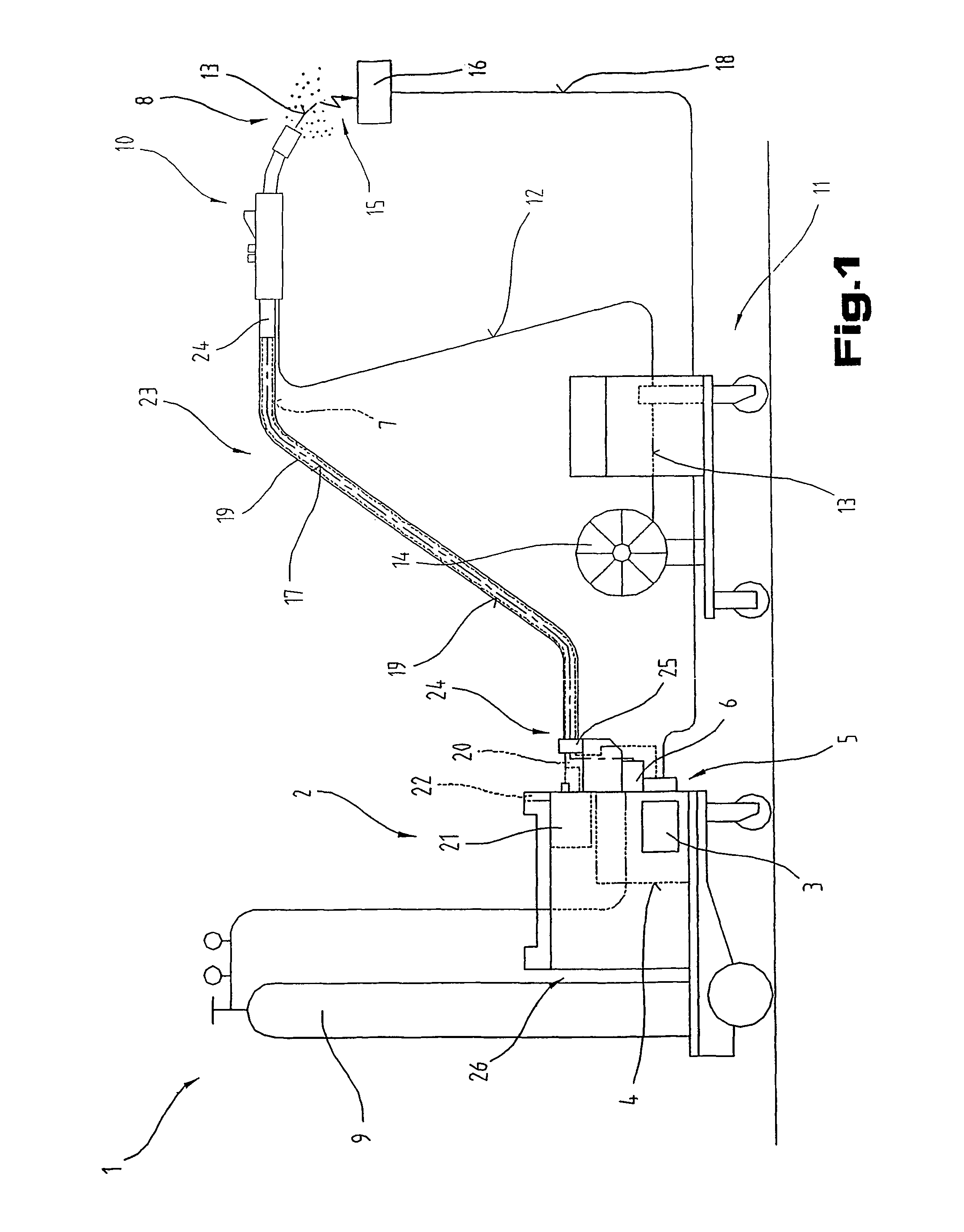
[0040]FIG. 1 shows a welder 1 or a welding system for greatly varying processes or methods, such as MIG / MAG welding or WIG / TIG welding or electrode welding methods, double wire / tandem welding methods, plasma or soldering methods, etc.

[0041]The welder 1 comprises a power source 2 having a power unit 3, a control device 4, and a switching element 5, which is assigned to the power unit 3 and / or the control device 4. The switching element 5 and / or the control device 4 is connected to a control valve 6, which is situated in a supply line 7 for a gas 8, in particular a protective gas such as CO2, helium, argon, or the like, between a gas reservoir 9 and a welding torch 10.

[0042]In addition, a wire feed device 11, which is typical for MIG / MAG welding, can be activated via the control device 4, an auxiliary material or a welding wire 13 being suppl...


PUM

PropertyMeasurementUnit
Diameteraaaaaaaaaa
Areaaaaaaaaaaa

Abstract

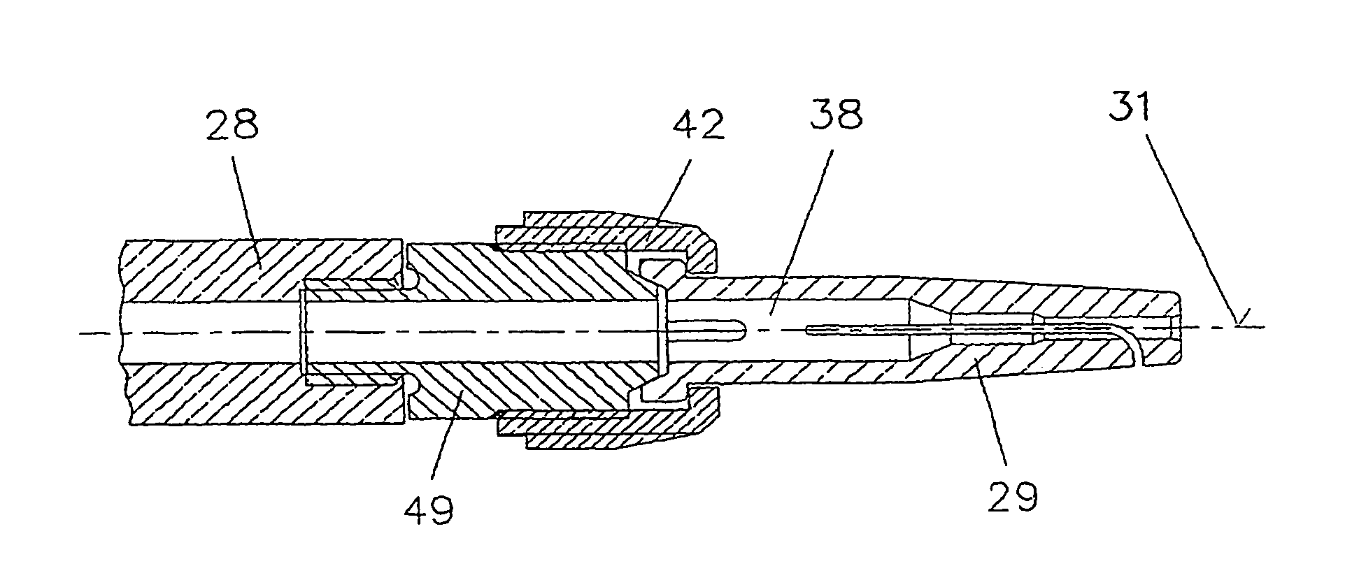
The invention relates to a contact tube (29) for a welding torch (10), having a longitudinal axis (31) along which a through-opening (30) for guiding a welding wire (13) from an inlet region (37) to an outlet region (35) and from an outlet opening (39) towards a workpiece (16) is provided, wherein at least one slot (34) is provided in the outlet region (35) for making contact with the welding wire (13). A contact tube (29) with improved contacting of the welding wire (13) is obtained by providing at least one further slot (36) in the inlet region (37) of the contact tube (29), wherein the slot (36) in the inlet region (37) is arranged in line with the slot (34) in the outlet region (35), and a web (38), which serves as a pivot point, is formed between the slot (34) in the outlet region (35) and the at least one slot (36) in the inlet region (37).

Description

CROSS REFERENCE TO RELATED APPLICATIONS[0001]This application is the National Stage of PCT / AT2009 / 000216 filed on May 25, 2009, which claims priority under 35 U.S.C. §119 of Austrian Application No. A 1034 / 2008 filed on Jun. 30, 2008, the disclosure of which is incorporated by reference. The international application under PCT article 21(2) was not published in English.BACKGROUND OF THE INVENTION[0002]1. Field of the Invention[0003]The invention relates to a contact tube for a welding torch, having a longitudinal axis, along which a continuous opening is provided for guiding a welding wire from an inlet area to an outlet area and from an outlet opening in the direction of a workpiece, at least one slot being provided in the outlet area for contacting the welding wire.[0004]All supplementary materials for greatly varying welding methods are included under the term welding wire.[0005]2. Description of the Related Art[0006]Manifold contact tubes for welding torches are known from the p...

Claims


Application Information

Patent Timeline
IPC IPC(8): B23K9/00
CPCB23K9/123
Inventor RUEHRNOESSL, MANFREDNOEBAUER, HARALDSTEINMAURER, MARKUS
Owner FRONIUS INTERNATIONAL GMBH
Learn More