Sputtering apparatus with rotatable sputtering target

a sputtering apparatus and target technology, applied in the field of sputtering technology, can solve the problems of time-consuming and inconvenien

Inactive Publication Date: 2011-07-21
HON HAI PRECISION IND CO LTD
View PDF7 Cites 1 Cited by
  • Summary
  • Abstract
  • Description
  • Claims
  • Application Information

AI Technical Summary

Problems solved by technology

This is inconvenient

Method used


Image

  • Sputtering apparatus with rotatable sputtering target
  • Sputtering apparatus with rotatable sputtering target
  • Sputtering apparatus with rotatable sputtering target

Examples


Embodiment Construction

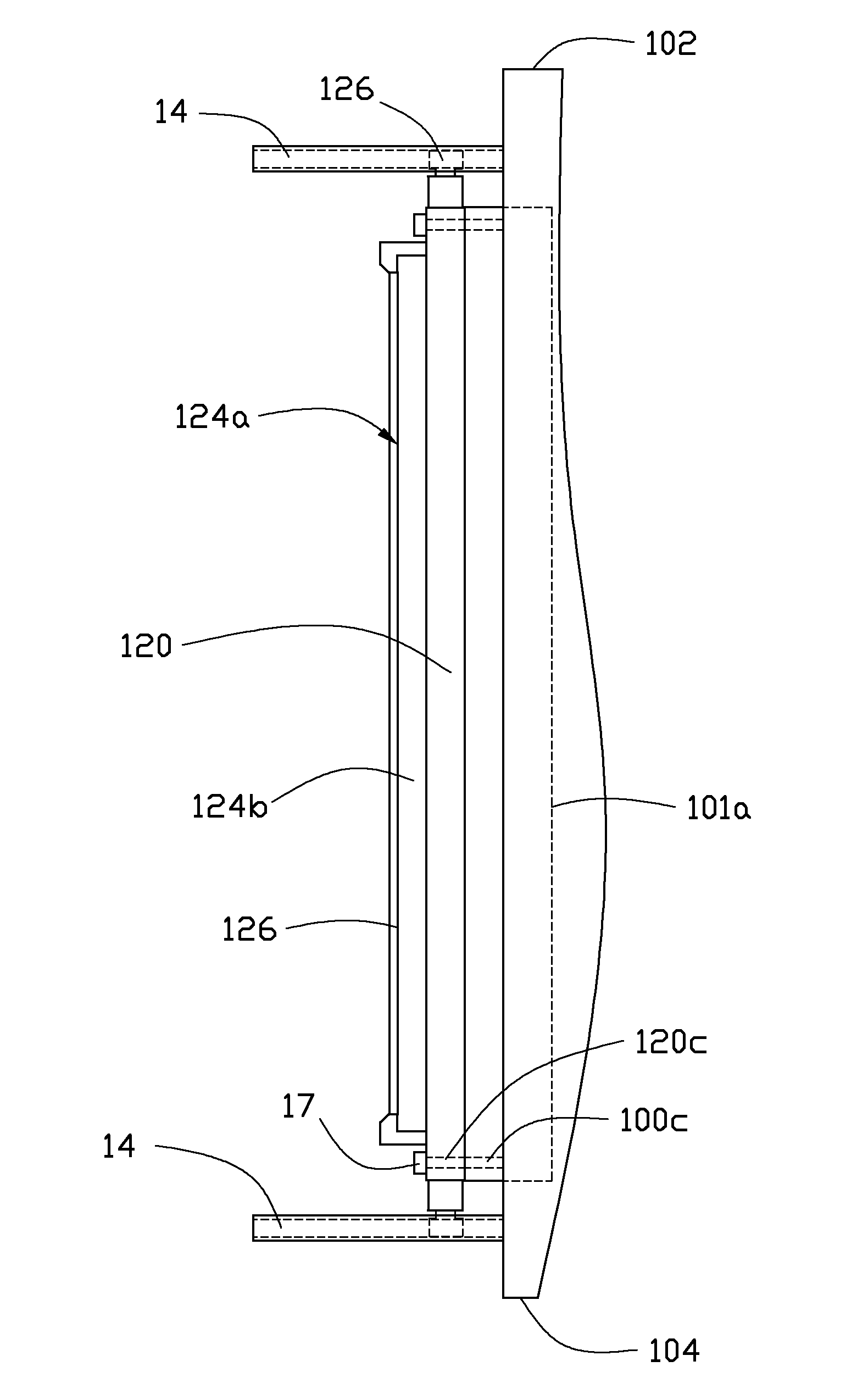
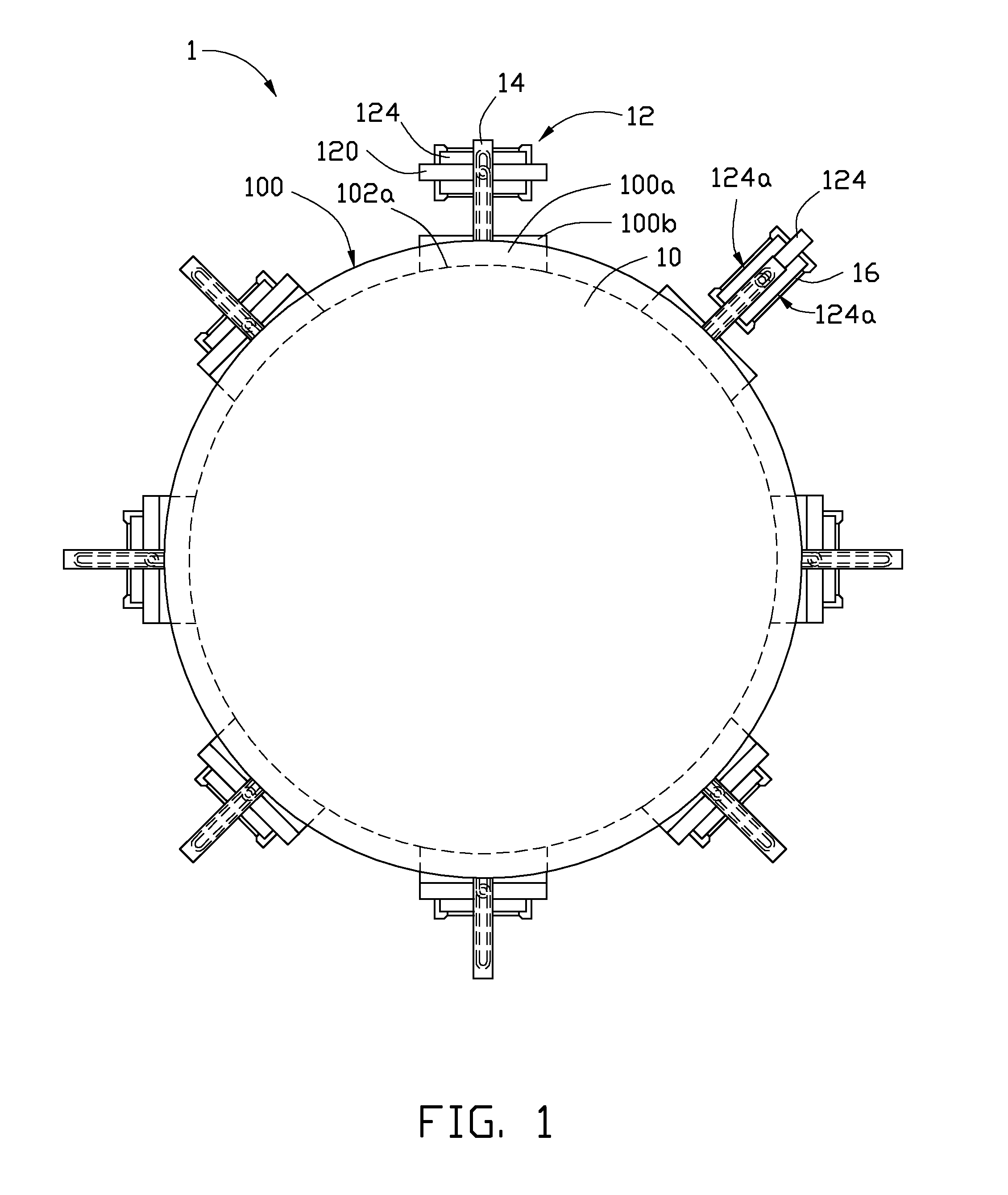
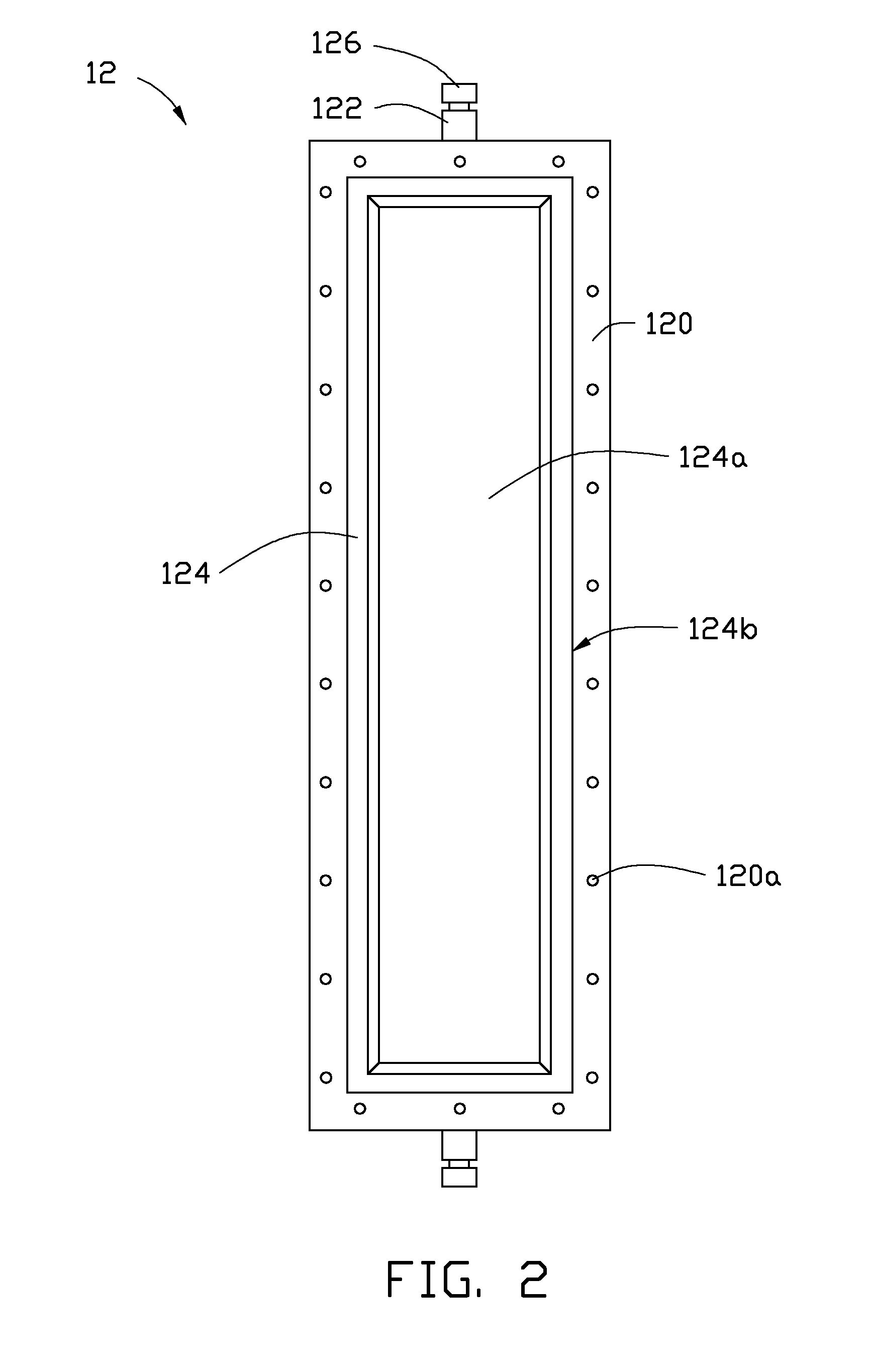
[0012]Referring to FIGS. 1 and 3, a sputtering apparatus 1 in accordance with one embodiment of the present disclosure is shown. The sputtering apparatus 1 includes a chamber 10, a number of target holders 12, a number of slide rails 14, and a number of sputtering targets 16.

[0013]The chamber 10 is substantially cylindrical and includes an upper cover 102, a bottom cover 104, a cylindrical first sidewall 100, and a number of connecting frames 100b. The upper cover 102 and the bottom cover 104 perpendicularly connect two opposite sides of the first sidewall 100, respectively. The chamber 10 defines a number of first through holes 100a radially arranged in the first sidewall 100 at predetermined intervals. Each first through hole 100a is substantially rectangular and defines a pair of long sides 101a and a pair of short sides 102a. The long sides are substantially parallel to a central axis of the chamber 10. Each connecting frame 100b perpendicularly protrudes from the first sidewall...


PUM


Abstract

A sputtering apparatus includes a chamber including a first sidewall and defining a number of evenly spaced first through holes on the first sidewall, a number of slide rails radially extending outwards from the first sidewall corresponding to each first through hole, a number of target holders defining at least two sputtering faces and slidably engaged with the slide rails, and a target material mounting on the sputtering faces. The target holder includes a shaft; the sputtering face capable of rotating about the shaft. The target holders are fastened to the first sidewall with one of the sputtering faces facing the first through hole, the sputtering face capable of being replaced by rotating about the shaft.

Description

BACKGROUND[0001]1. Technical Field[0002]The present disclosure relates generally to the field of sputtering technology, and more particularly, to a sputtering apparatus with rotatable sputtering target capable of replacing a target material easily and rapidly.[0003]2. Description of Related Art[0004]Sputtering is a physical vapor deposition (PVD) process whereby atoms in a solid target material are ejected into the gas phase due to bombardment of the material by energetic ions. With advantages such as good deposition efficiency, precise deposition control and relative low cost, sputtering has become a popular deposition process in industry.[0005]Generally, a typical sputtering apparatus includes a chamber, a target holder, and a target material. The target material is positioned on the target holder. The target holder is fastened in the chamber. When the target material on the target holder is required to be changed, the target holder is typically detached from the chamber before a ...

Claims


Application Information

Patent Timeline
IPC IPC(8): C23C14/34
CPCC23C14/3407H01J37/3435H01J37/3414
Inventor WU, CHIA-YING
Owner HON HAI PRECISION IND CO LTD
Why Eureka
Try Eureka