Tank with an integral filter and beverage dispensing appliance comprising such a tank
a beverage and tank technology, applied in gravity filters, liquid dispensing, water treatment locations, etc., can solve the problems of difficulty in accessing the different elements, long, complex and detailed intervention, and leaving aside the risk of running out of large-capacity bottles, etc., to achieve the effect of replacing the dispensing water circuit easily and quickly
- Summary
- Abstract
- Description
- Claims
- Application Information
AI Technical Summary
Benefits of technology
Problems solved by technology
Method used
Image
Examples
second embodiment
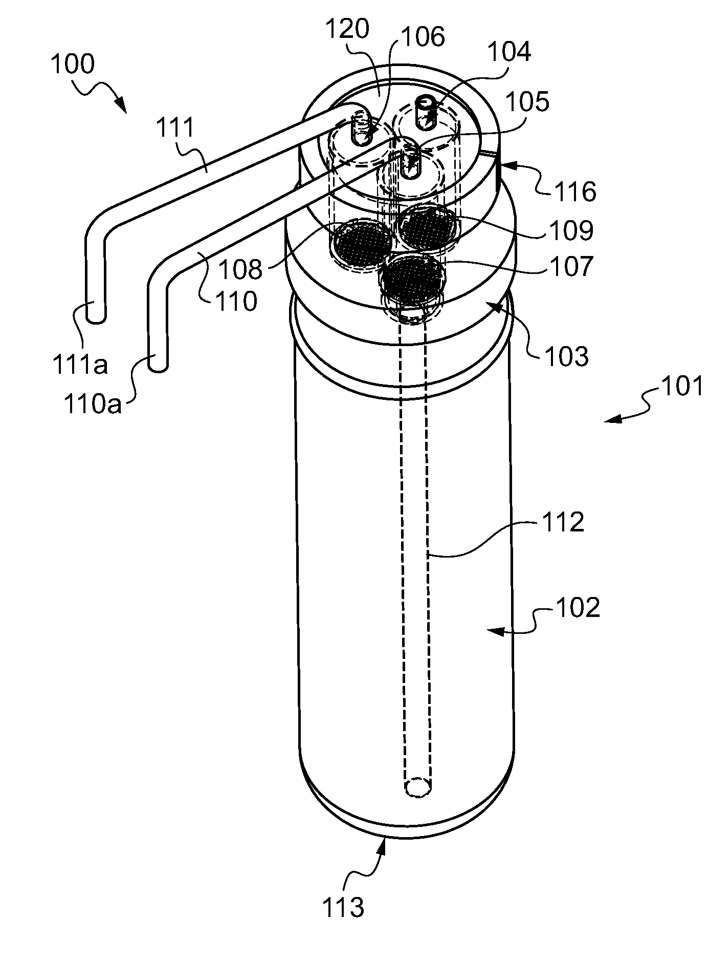
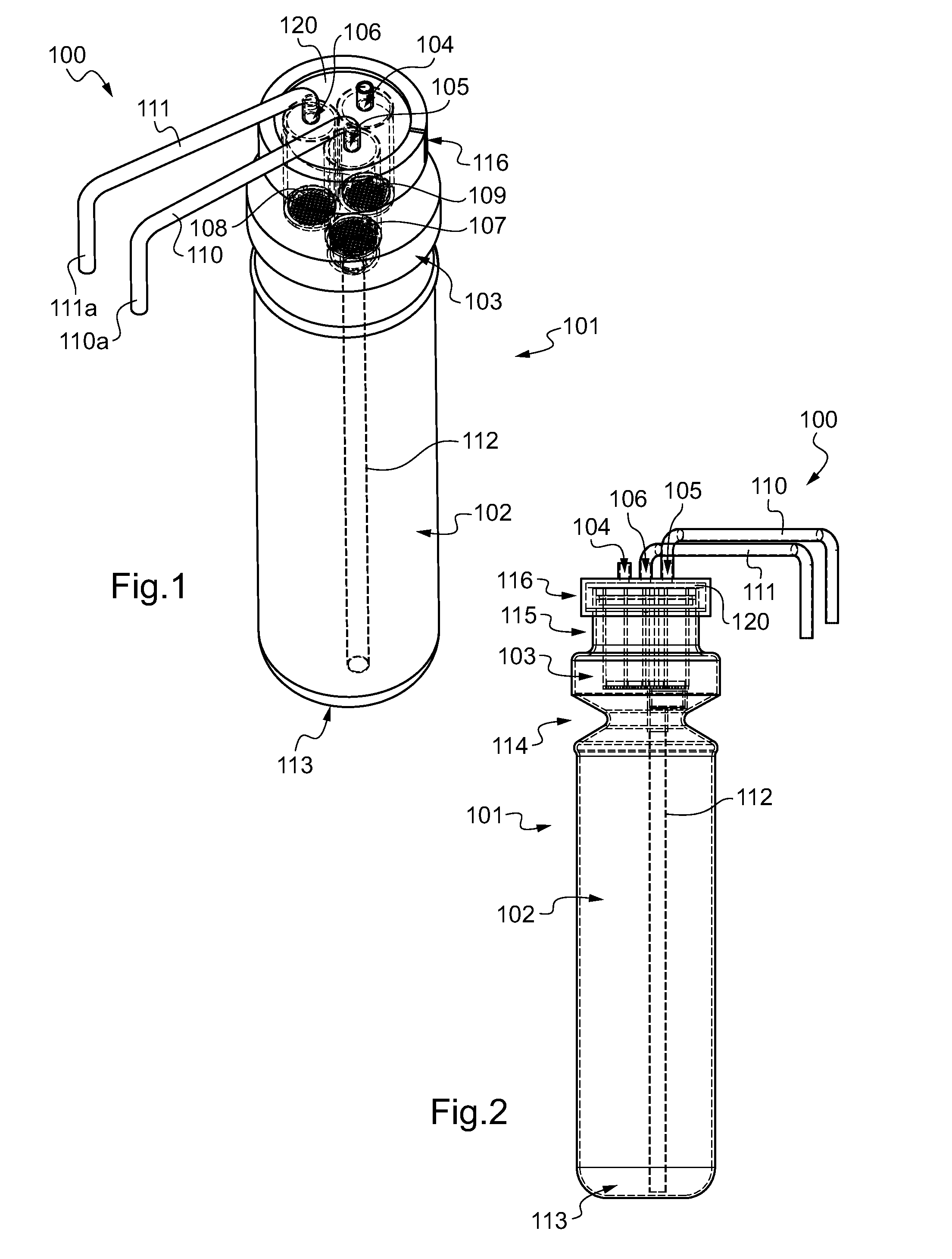
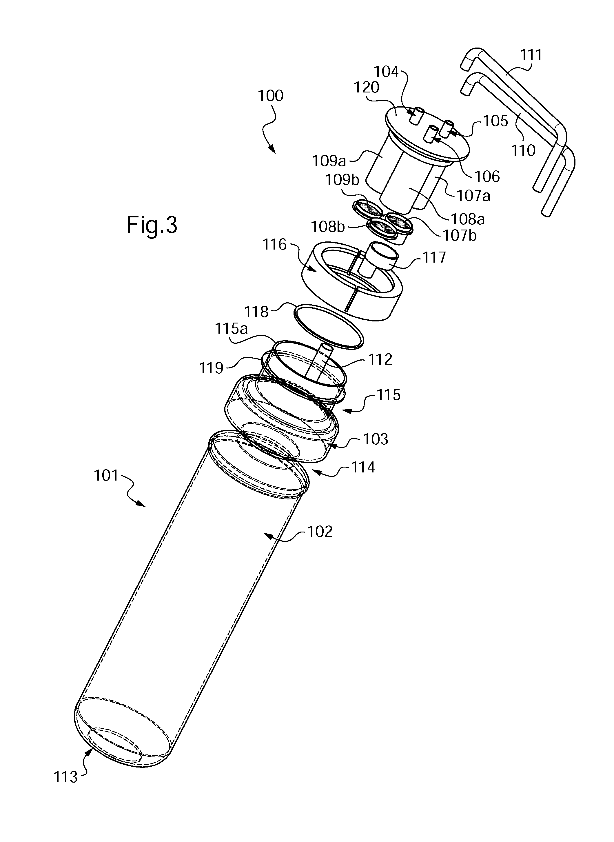
[0126]FIGS. 10 and 11 show a tank according to the invention. The common elements in the example previously shown are not described again. This second example differs from the first in that the unit 100 is here situated above the neck 115. To this end, the unit 100 also comprises a casing 121, here cylindrical overall with a circular cross section. The casing 121 is closed on the upper part by the platform 120, and comprises a lower part 122 enlarged to form the second chamber 103 and suitable for cooperating with the neck 115, for example to be fixed thereto in a manner that does not allow disassembly by legs 122′ allowing the unit 100 to be snap-connected onto the neck 115. Thus, it is noted here that the second chamber 103 is formed by the unit 100 and not by the body of the tank per se as in the previous example. The neck 115 here serves as a narrowing 114 between the first chamber 102 and the second chamber 103. As previously, the platform 120 here has a lower face from which e...
third embodiment
[0127]FIG. 12 shows a tank according to the present invention, The common elements in the example shown in FIGS. 1 to 5 are not described again. This embodiment differs for example from that in FIGS. 1 to 5 in that the taps 208, 208′ are positioned directly over the openings 105, 106. In this embodiment, the actuator of the tap 208 (or of the tap 208′ which is identical thereto) is for example simply constituted by a button 214 (or 214′) constricting the pipe 110 (or 111) when it is in the off position. Such an embodiment makes it possible for example to have an extremely compact tank 101. Preferably, the tap 208 (or 208′) is mounted on the tank in such a way that it cannot be disassembled, i.e. so that the tank 101 is at least partially damaged if the tap is subjected to attempted disassembly, for example by bonding, snap-connecting or other means. Such tank is for example intended for an appliance similar to that shown in FIGS. 13 to 15.
[0128]FIGS. 13, 14 and 15 show a dispensing ...
fourth embodiment
[0129]FIGS. 16 to 19 show a tank 101 according to the present invention. The common elements in the example shown in FIGS. 1 to 5 are not described again. Such a tank 101 differs from the embodiment in FIGS. 1 to 5 in that it comprises moreover a compact dispensing assembly 123. This assembly 123 here comprises for example a UV sterilizer 217 connected to the single tap 208. Such a sterilizer, well known to a person skilled in the art, is not described in detail here. A plug 124 makes it possible for example to connect it to an electrical connection 219a of an appliance 200 as previously shown. The plug 124 makes it possible for example to electrically supply the UV sterilizer 217. A fluidic connector 125 makes it possible for example to connect the tank 101 to a fluidic connector 219b of an appliance 200 as shown previously. The fluidic connector 125 here comprises three connectors 125a, 125b, 125c, intended to cooperate with the three orifices of the fluidic connector 219b. A firs...
PUM
| Property | Measurement | Unit |
|---|---|---|
| temperature | aaaaa | aaaaa |
| diameters | aaaaa | aaaaa |
| diameters | aaaaa | aaaaa |
Abstract
Description
Claims
Application Information
 - R&D
- Intellectual Property
- Life Sciences
- Materials
- Tech Scout
- Unparalleled Data Quality
- Higher Quality Content
- 60% Fewer Hallucinations
Browse by: Latest US Patents, China's latest patents, Technical Efficacy Thesaurus, Application Domain, Technology Topic, Popular Technical Reports.
© 2025 PatSnap. All rights reserved.Legal|Privacy policy|Modern Slavery Act Transparency Statement|Sitemap|About US| Contact US: help@patsnap.com


