Backside accessible display

a technology of backside and display, which is applied in the direction of semiconductor devices for light sources, lighting and heating apparatus, lighting support devices, etc., can solve the problems of inconvenient maintenance and replacement of failure diodes, and achieve the effect of convenient and rapid in-out and out of the light board, and convenient change of different color light units

Active Publication Date: 2009-07-07
CHENG KUNG CAPITAL LLC
View PDF2 Cites 2 Cited by
  • Summary
  • Abstract
  • Description
  • Claims
  • Application Information

AI Technical Summary

Benefits of technology

[0006]The primary object of the present invention is to prepare a light board that is convenient for assembly and disassembly of the light units from a backside of the light board. A second object of the present invention is to provide a light board that is easily to be maintained for changing different color light units, or changing different displaying patterns. A third object of the present invention is to provide a light board that allows easy and rapid replacement of a failure light unit from the backside of the light board.
[0009]The present invention uses a light board that has a first opening on a first metal for light emitting and a second opening on a second metal for insertion of the light unit, and it is convenient to change different color light units, and it is easy and rapid in and out of the light board to remove or replace a failure light unit from backside of the light board.

Problems solved by technology

The shortcomings of the prior art are as follows: (1) inflexibility in color changing, i.e., it is impossible or inconvenient to change different light color chips at any moment; (2) inconvenience of maintaining and replacing a failure diode chip.

Method used


Image

  • Backside accessible display
  • Backside accessible display
  • Backside accessible display

Examples


Embodiment Construction

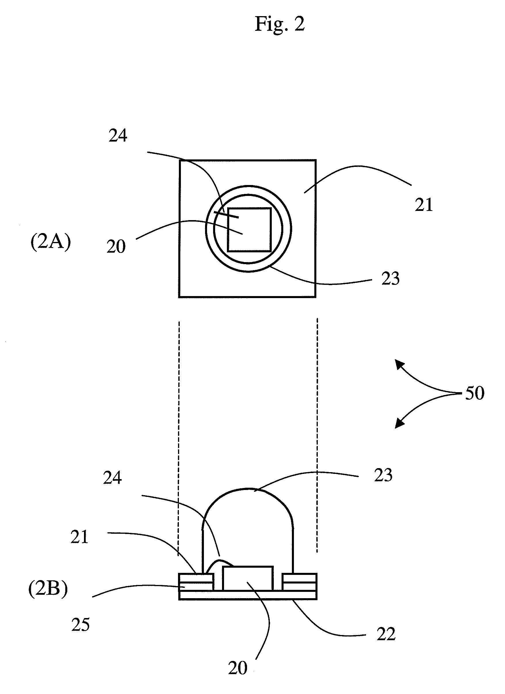
[0023]FIG. 2A is a top view of a light unit 50 used in the present invention. It shows a cassette light unit 50 that encapsulates a light-emitting diode chip 20. The light unit 50 has a pedestal with a top metal 21 and a bottom metal 22. The first electrode or surface electrode of the light-emitting diode chip 20 is electrically coupled with the top metal 21 through a bonding wire 24. The top metal 21 has an open area at its center for mounting a light-emitting diode chip 20 onto the top surface of bottom metal 22. The second electrode or bottom electrode of the light-emitting diode chip 20 is electrically coupled with the bottom metal 22. A transparent glue 23 is coated above the light-emitting diode chip 20 for modifying the emitted light and to ensure the reliability of the product. Double wire bonding can be used to couple the two electrodes respectively to the top metal 21 and the bottom metal 22 if the LED 20 has two surface electrodes.

[0024]FIG. 2B is a side view of the light...


PUM


Abstract

A light board is made with a receptacle substrate for holding cassette light units. The convenience of assembly and disassembly of the light units from the receptacle substrate makes the product easily to be maintained for changing different color light units, changing different displaying patterns, and removing or replacing a failure light unit.

Description

RELATED APPLICATIONS[0001]The present application is based on, and claims priority from, Taiwan Application Serial Number 095109372, filed Mar. 20, 2006, the disclosure of which is hereby incorporated by reference herein in its entirety.BACKGROUND OF THE INVENTION[0002]1. Field of the Invention[0003]This invention relates to a matrix display of light emitted diodes with a backside that is accessible for light unit insertion and maintenance.[0004]2. Description of the Related Art[0005]FIG. 1 is a traditional light board. The conventional light board is a printed circuit board (PCB) 10 with a plurality of light-emitting diode (LED) chips 11, only one LED 11 is shown in FIG. 1, each of the diodes has bottom metals 11a and 11b. Corresponding metal circuits 10a and 10b are provided on the board 10 to electrically couple with the electrodes 11a and 11b of the light-emitting diode chip 11 respectively to form a traditional light-emitting diode display board. The shortcomings of the prior a...

Claims


Application Information

Patent Timeline
Patent Type & Authority Patents(United States)
IPC IPC(8): F21V21/00H01L33/62
CPCF21K9/00F21V19/042F21V19/001F21Y2101/02H01L33/62Y10S362/80H01L2224/48091H01L2924/00012F21V19/004F21V19/04F21Y2115/10
Inventor WU, JIAHN-CHANG
Owner CHENG KUNG CAPITAL LLC
Why Eureka
Try Eureka