Detachable lamp socket

a lamp socket and detachable technology, applied in the direction of semiconductor devices for light sources, coupling device connections, lighting and heating apparatus, etc., can solve the problems of inconvenient use, spiral-type lamp sockets are not usable, limited use of lighting devices, etc., and achieve the effect of convenient disassembly and assembly

Inactive Publication Date: 2011-08-23
MAINHOUSE (XIAMEN) ELECTRONICS CO LTD
View PDF26 Cites 50 Cited by
  • Summary
  • Abstract
  • Description
  • Claims
  • Application Information

AI Technical Summary

Benefits of technology

[0005]The primary object of the present invention is to provide a detachable lamp socket, which is firm and convenient for disassembly and assembly and used widely.
[0009]The feature of the present invention is that the top of the housing is provided with the engaging groove and the bottom of the contact member is provided with the hooks. With the hooks and the engaging groove, the contact member and the housing are connected together. The notch of the engaging groove is open, such that the hooks of the contact member are levelly pushed in the engaging groove. This can prevent a lamp base from being loosened when rotating a lamp, so that the contact member and the housing are connected firmly. Furthermore, this connection way is very convenient for disassembly and assembly. The contact member of the present invention can be replaced for snap-in lamp bases and spiral-type lamp bases, which is used widely.

Problems solved by technology

Because the specification and shape of the lamp socket is different, the lighting device is limited when in use.
For example, if the lamp base is in a snap-in type, a spiral-type lamp socket is not usable.
This is not convenient for use.
However, the connection of the contact member and the housing is not firm, and it is not convenient to disassemble and assemble the lamp.

Method used


Image

  • Detachable lamp socket
  • Detachable lamp socket
  • Detachable lamp socket

Examples


Embodiment Construction

[0020]Embodiments of the present invention will now be described, by way of example only, with reference to the accompanying drawings.

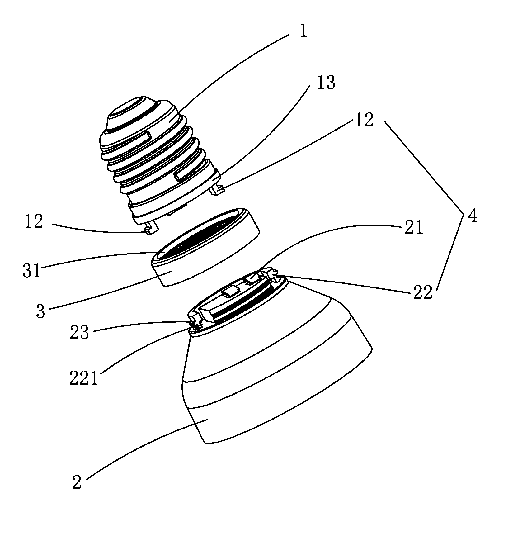
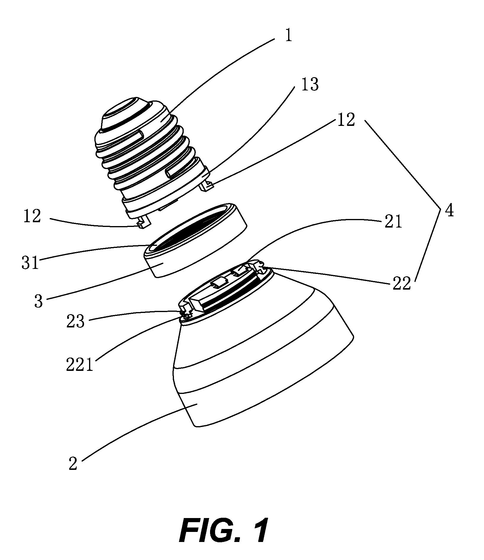
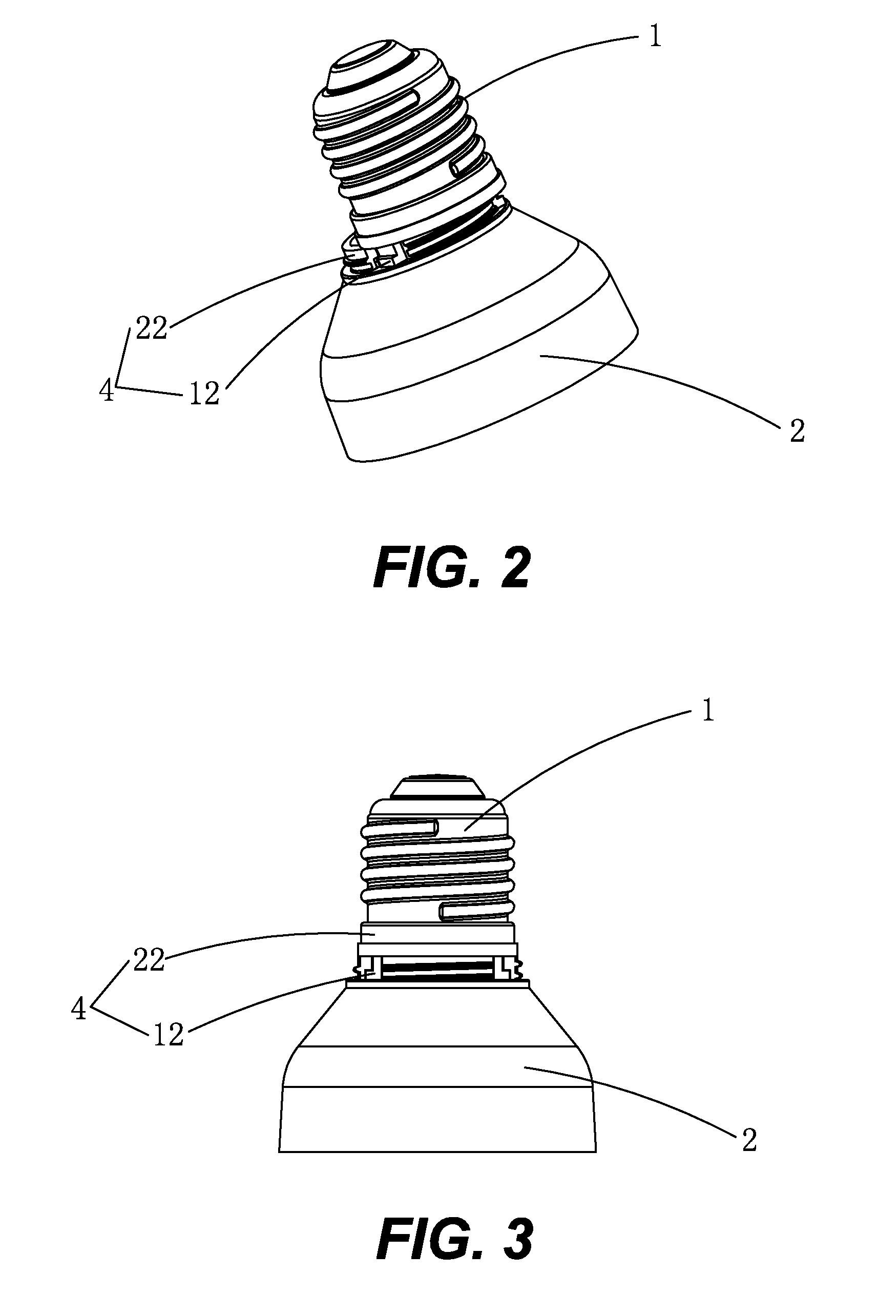
[0021]As shown in FIG. 1, the detachable lamp socket of the present invention comprises a contact member 1, a housing 2, and a fixing ring 3.

[0022]A lower end of the contact member 1 is connected to an upper end of the housing 2. The fixing ring 3 is fitted on the junction of the contact member 1 and the housing 2 so as to fix the contact member 1 and the housing 2. A first conductive element 11 disposed in the contact member 1 is electrically connected to a second conductive element 21 disposed in the housing 2, as shown in FIG. 6C. A resilient plate is used to connect the conductive elements.

[0023]A bottom of the contact member 1 and a top of the housing 2 are respectively provided with engaging portions 4 for engagement. The engaging portions 4 comprise an annular engaging groove 22 disposed on the top of the housing 2 and three hooks 12 extending ...


PUM


Abstract

A detachable lamp socket includes a contact member (1), a housing (2), and a fixing ring (3). A lower end of the contact member (1) is connected to an upper end of the housing (2). The fixing ring (3) is fitted on the junction of the contact member (1) and the housing (2) to fix the contact member (1) and the housing (2). The top of the housing (2) is provided with the engaging groove (22) and the bottom of the contact member (1) is provided with hooks (12). With the hooks (12) and the engaging groove (22), the contact member (1) and the housing (2) are connected together. The notch (221) of the engaging groove (22) is open, such that the hooks (12) of the contact member (1) are levelly pushed in the engaging groove (22). The fixing ring (3) may be threaded onto outer threads (23) of the housing (2) to complete the assembly. This can prevent a lamp base from being loosened when rotating a lamp, so that the contact member (1) and the housing (2) are connected firmly. Furthermore, this connection way is very easy, quick and convenient for disassembly and assembly.

Description

BACKGROUND OF THE INVENTION[0001]1. Field of the Invention[0002]The present invention relates to a lighting device, and more particularly to a detachable lamp socket.[0003]2. Description of the Prior Art[0004]A conventional energy-saving lamp for a lighting device comprises a lamp socket fixed on the lamp. Because the specification and shape of the lamp socket is different, the lighting device is limited when in use. For example, if the lamp base is in a snap-in type, a spiral-type lamp socket is not usable. Besides, the diameter of the lamp base must match with the diameter of the lamp socket. This is not convenient for use. Therefore, there are various detachable and assembled lamp sockets on the market. The applicant of the present invention has filed many applications for detachable and replaceable lamp sockets. The detachable and replaceable lamp socket comprises a contact member, a housing which is detachably connected to the contact member, and a fixing ring to fix the contac...

Claims


Application Information

Patent Timeline
Patent Type & Authority Patents(United States)
IPC IPC(8): H01R31/02
CPCF21K9/00F21V19/04H01R33/22H01R33/94H01R13/625H01K1/48
Inventor ZHOU, NAN-QING
Owner MAINHOUSE (XIAMEN) ELECTRONICS CO LTD
Why Eureka
Try Eureka