Accessory rail trigger guard holster

a technology for accessory rails and trigger guards, which is applied in the field of trigger guards, can solve the problems of not being able to easily install or remove clip holsters, requiring the addition of parts that may affect the performance of firearms, and not having a combination trigger guard and clip holster that attaches to the accessory rail of firearms. , to achieve the effect of convenient installation and removal, retaining effectiveness, and being easy to manufacture and maintain

Inactive Publication Date: 2006-04-18
VIANI ARTHUR
View PDF4 Cites 18 Cited by
  • Summary
  • Abstract
  • Description
  • Claims
  • Application Information

AI Technical Summary

Benefits of technology

[0011]The instant invention has integral trigger guards defined as guard walls. The guard walls prevent the accidental firing of the firearm when the firearm is worn with the clip holster in the person's waistband.
[0015]It is therefore one of the main objects of the present invention to provide an accessory rail trigger guard holster to protect the user by preventing the trigger from unintended contact with objects, which would cause unintentional or accidental firing of the firearm when carried or used.
[0016]It is another object of this invention to provide an accessory rail trigger guard holster that mounts upon the accessory rail, enabling a person to carry a firearm safely inside a waistband or attached to an object without the danger of an unintentional or accidental discharge.
[0018]It is yet another object of this invention to provide an accessory rail trigger guard holster that is readily installable and removable, requires no additional parts for it to function or tools to install or remove.
[0019]It is yet another object of this invention to provide such a device that is inexpensive to manufacture and maintain while retaining its effectiveness.

Problems solved by technology

These methods are adequate, but require the addition of parts that may affect the performance of the firearm.
Furthermore, these types of clip holsters are not readily installable or removable.
However, there are no combination trigger guard and clip holster that attach to the accessory rails of a firearm, and that can be carried safely in their intended manner without the danger of unintentional or accidental discharge of the firearm.
More specifically, none of these patents suggest use of an existing firearm's accessory rail for mounting of a trigger guard holster.

Method used


Image

  • Accessory rail trigger guard holster
  • Accessory rail trigger guard holster
  • Accessory rail trigger guard holster

Examples


Embodiment Construction

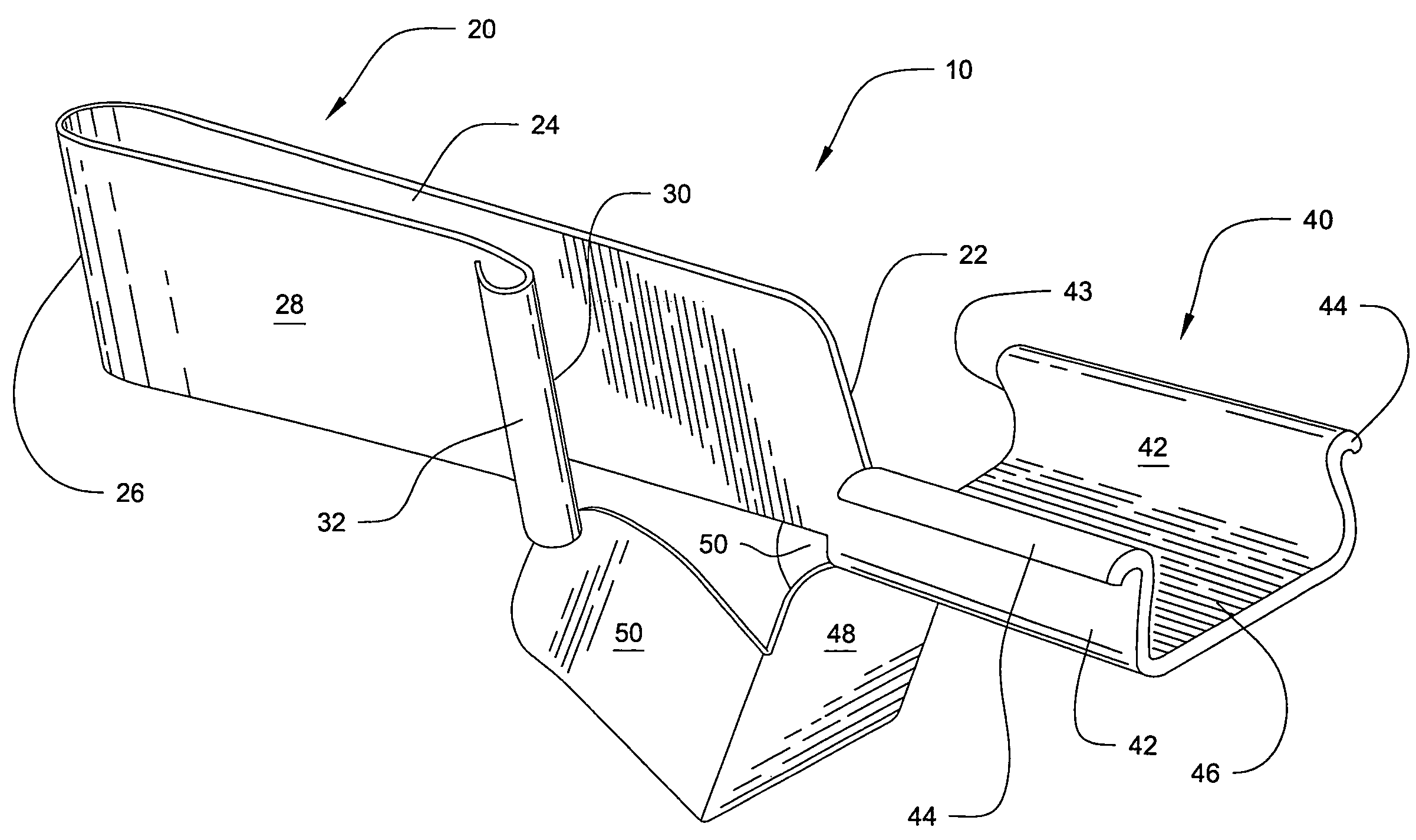
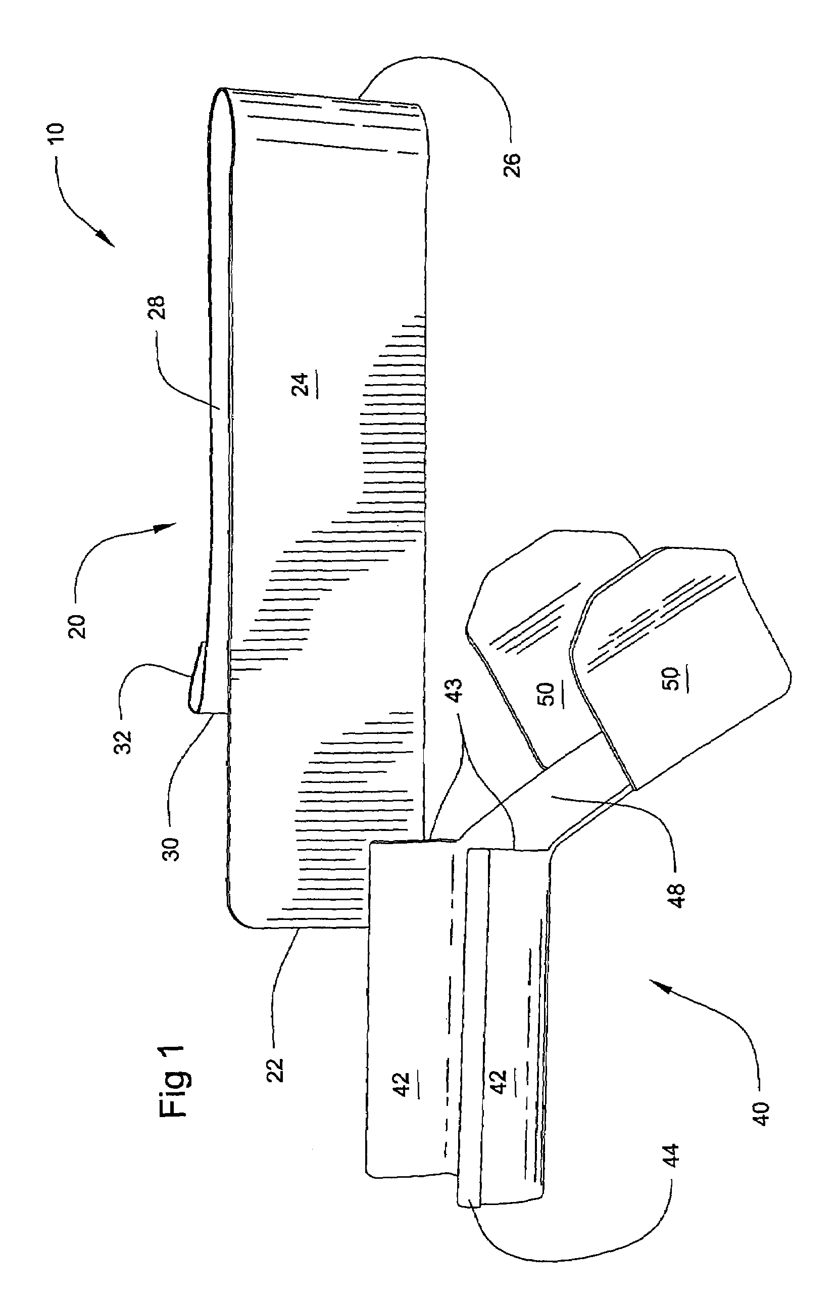
[0029]Referring now to the drawings, where the present invention is generally referred to with numeral 10, it can be observed that it basically includes clip holster 20 and trigger guard assembly 40.

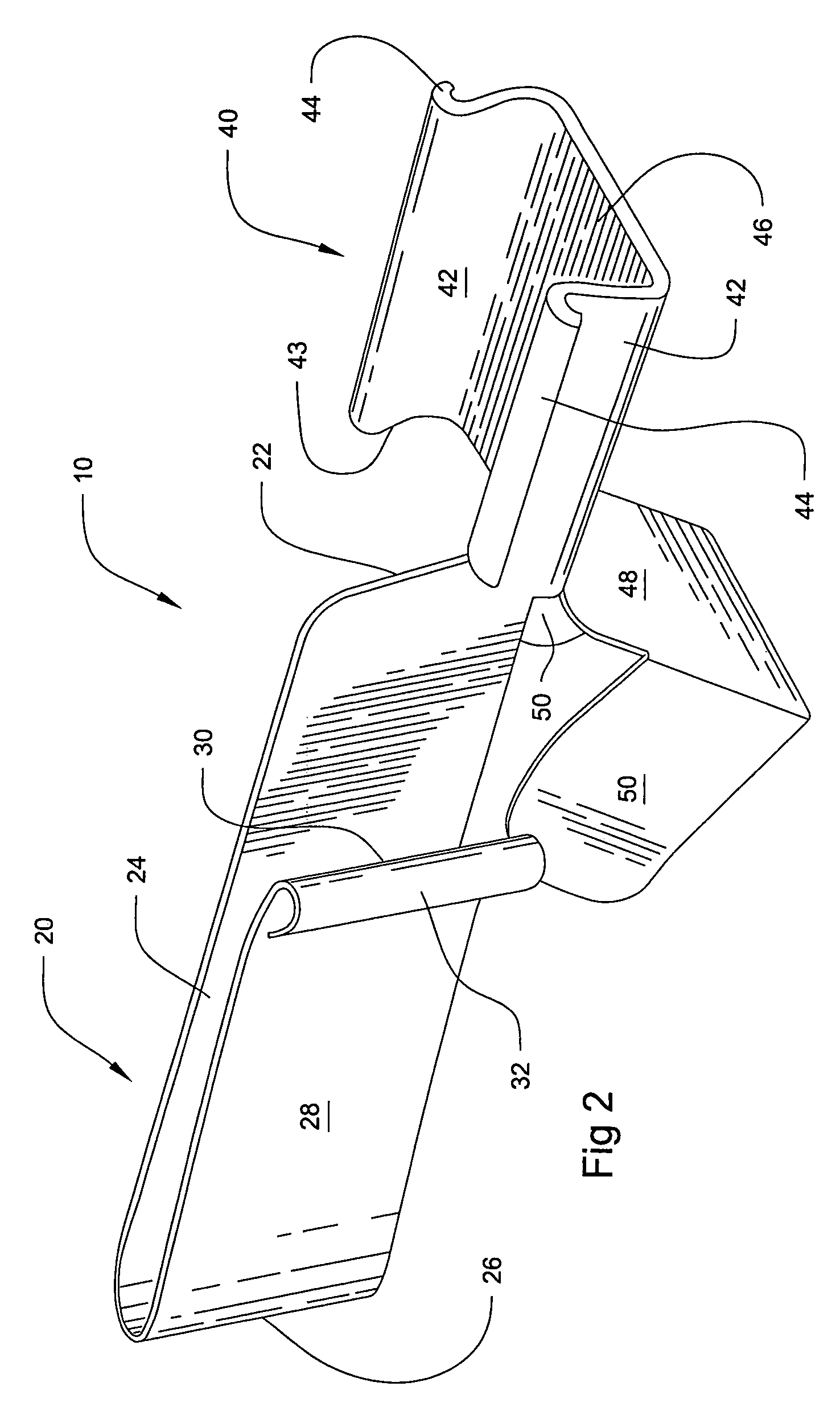
[0030]As seen in FIGS. 1 and 2, clip holster 20 comprises straight-arm 24 and tension arm 28 generally parallel to one another and joined at bend 26. Straight-arm 24 terminates at end 22 and tension arm 28 terminates at lip 32 that has a bend 30.

[0031]As better seen in FIG. 2, extending from clip holster 20, and more specifically straight-arm 24, is trigger guard assembly 40. Trigger guard assembly 40 comprises parallel and spaced apart sidewalls 42 extending from base wall 46. Sidewalls 42 terminate with lips 44. It is noted that sidewalls 42 incline slightly towards each other, wherein the distance between sidewalls 42 at base wall 46 is slightly greater than the distance between lips 44.

[0032]Extending at a predetermined angle from base wall 46 is mount wall 48. Perpendicularly extend...


PUM


Abstract

A trigger guard holster comprising a combination clip holster and trigger guard assembly that mounts upon an existing accessory rail of a firearm. The trigger guard assembly has guard walls to prevent the accidental firing of a firearm when the firearm is worn with the clip holster in a person's waistband. The trigger guard assembly also protects the person by preventing the trigger from unintended contact with objects, which would cause unintentional or accidental firing of the firearm when carried or used.

Description

BACKGROUND OF THE INVENTION[0001]1. Field of the Invention[0002]The present invention relates to trigger guards, and more particularly, relates to a trigger guard that mounts upon a firearm's accessory rail and serves as a clip holster.[0003]2. Description of the Related Art[0004]Trigger guards have been used to prevent the accidental discharge of firearms. Clip holsters have been used as a method of holding a firearm on one's person. There are many varieties of dip holsters. Some are integral to the grip stocks of a firearm, and others utilize pins and screws to attach the clip holster to the firearm. These methods are adequate, but require the addition of parts that may affect the performance of the firearm. Furthermore, these types of clip holsters are not readily installable or removable. More importantly however, there is a history of these types of dip holsters that permit a firearm to fire when worn by the person in their intended manner, inside the person's waistband.[0005]S...

Claims


Application Information

Patent Timeline
Patent Type & Authority Patents(United States)
IPC IPC(8): F41A17/00F41C33/00
CPCF41A17/54
Inventor VIANI, ARTHUR
Owner VIANI ARTHUR
Why Eureka
Try Eureka