
Quick-release joint for two tubes

a technology of two tubes and quick release, which is applied in the direction of couplings, screws, rod connections, etc., can solve the problems of misalignment or loose engagement between the first tube and the fastener easily breaking

Inactive Publication Date: 2006-04-18
LIN JONG TE
View PDF11 Cites 25 Cited by
  • Summary
  • Abstract
  • Description
  • Claims
  • Application Information

AI Technical Summary

Benefits of technology

"The present invention provides an improved quick-release joint for two tubes. The joint includes two connectors that are axially offset from each other and a retainer that aligns the connectors. The first connector has a protrusion with a groove, and the second connector has an internal lip that corresponds to the groove. When the connectors are engaged, the lip securely attaches to the groove, securing the connection between the tubes. The technical effect of this invention is to provide a reliable and secure connection between two tubes that can easily disengage when needed."

Problems solved by technology

However, when reviewing the engagement of the cover with both the first coupler and the second coupler, it is noted that the engagement between the first coupler and the second coupler merely depends on the cover and hinge so that after a period of time continuously bearing the force of maintaining the engagement between the first coupler and the second coupler, the fastener easily breaks or there will be misalignment or loose engagement between the first tube and the second tube due to the wear of the fastener.

Method used


Image

  • Quick-release joint for two tubes
  • Quick-release joint for two tubes
  • Quick-release joint for two tubes

Examples


Embodiment Construction

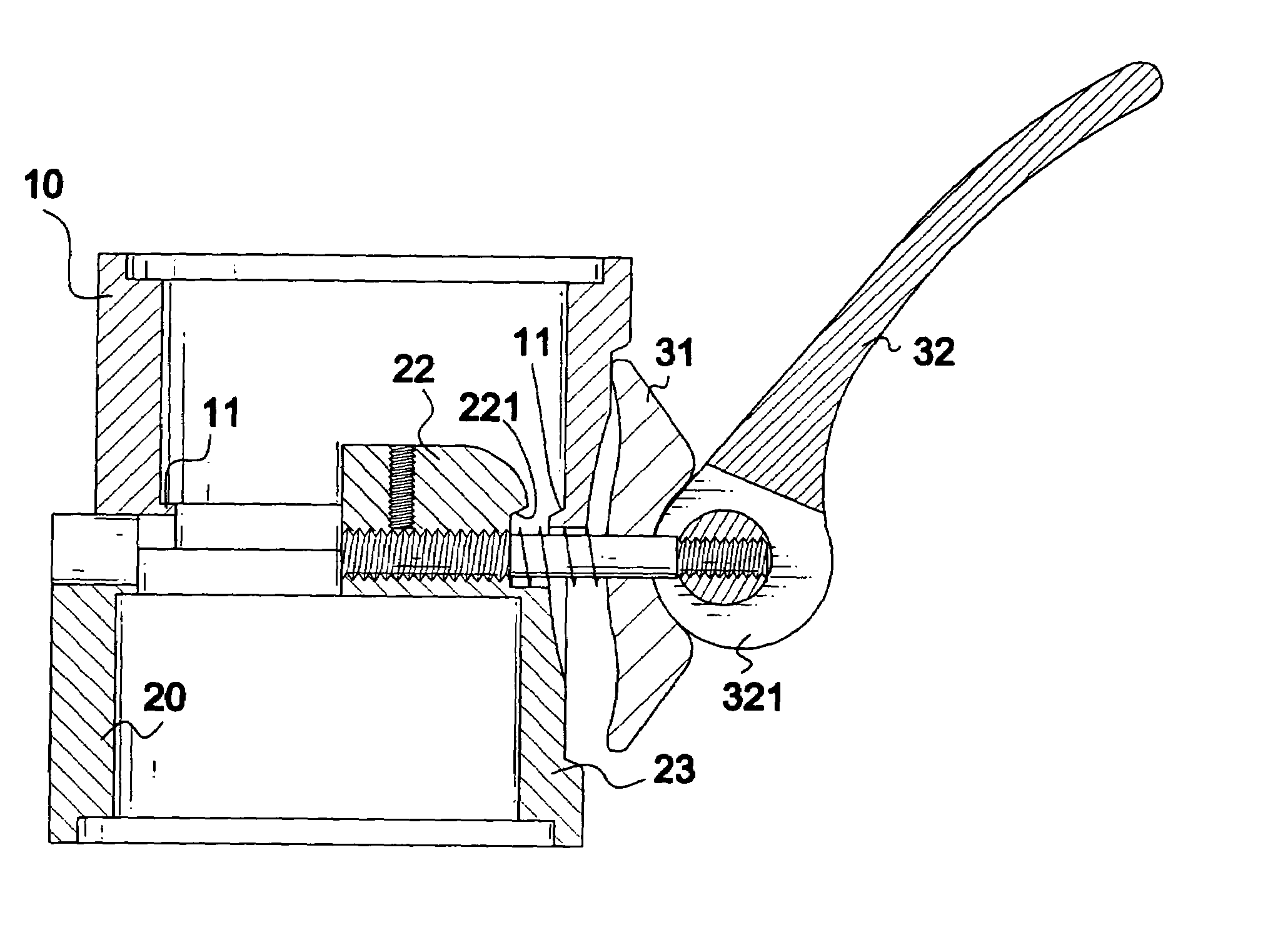
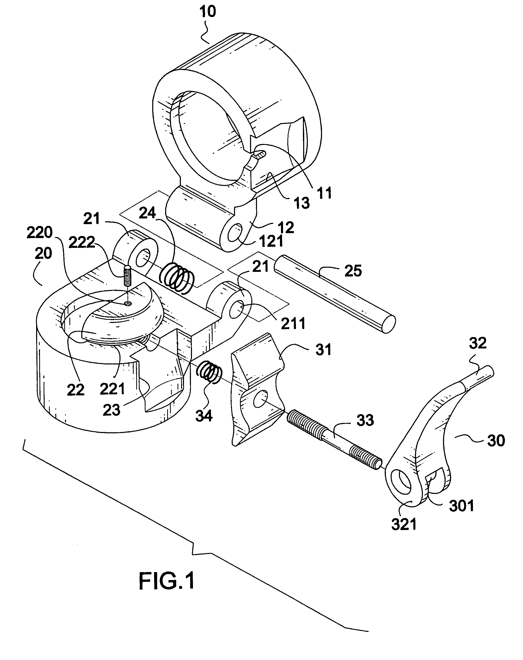
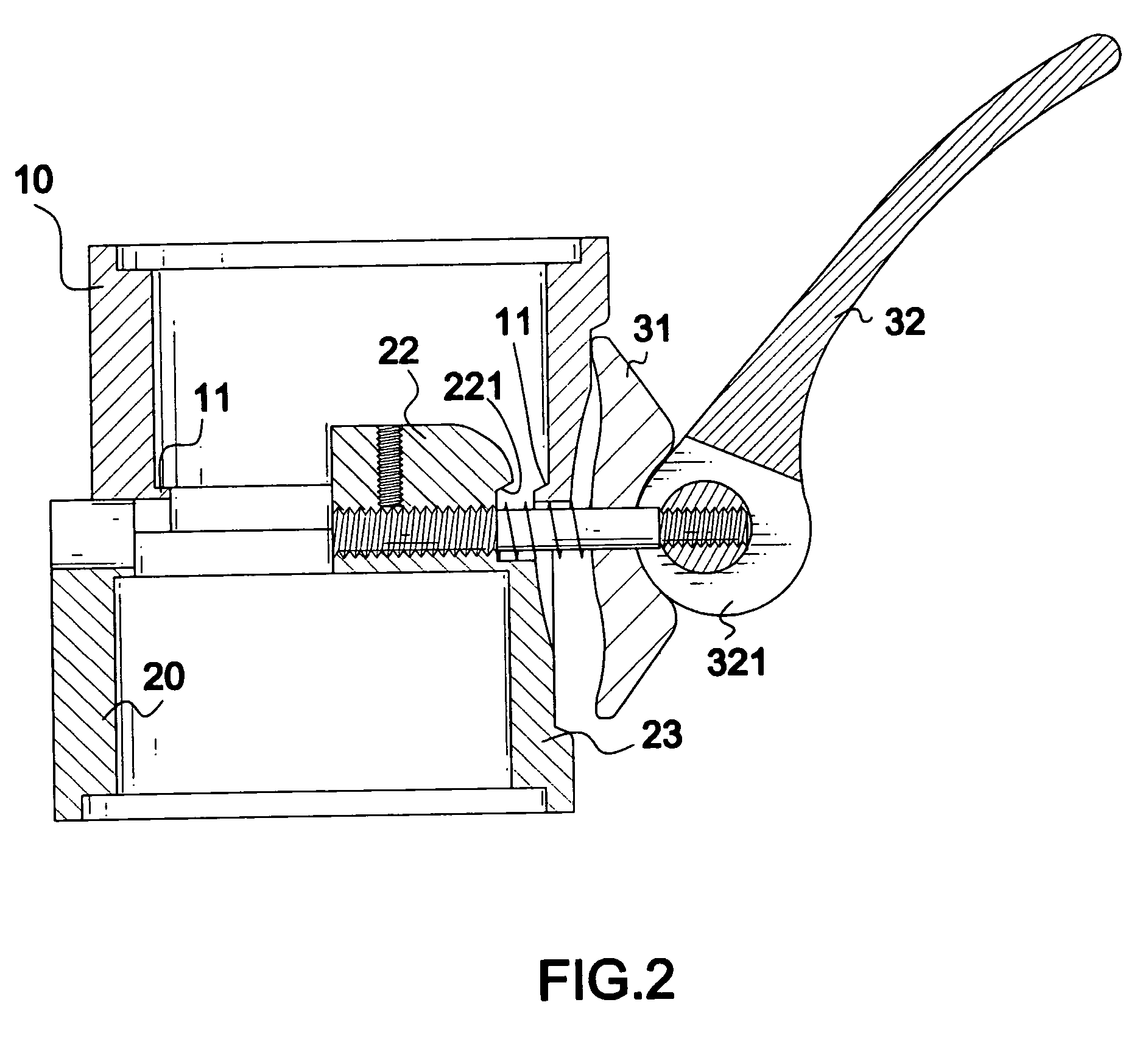
[0016]With reference to FIG. 1, the quick-release joint in accordance with the present invention has a first connector (10), a second connector (20) and a retainer (30).

[0017]The first connector (10) is adapted to securely connect to a first tube (not shown) and the second connector (20) is adapted to securely connect to a second tube (not shown). The purpose of the first connector (10) and the second connector (20) is to couple the first tube and the second tube in a strong, rigid manner.

[0018]The first connector (10) is a tubular object and has an internal lip (11) formed on an inner surface of the first connector (10) and a sleeve (12) formed on a side surface of the first connector (10). The sleeve (12) has a through-hole (121) on a common axis with the through-holes (211) on ears (21) of the second connector (20). Preferably, the internal lip (11) is inclined with respect to an inner face of the first connector (10). A first recessed area (13) is defined in an outer surface of ...


PUM


Abstract

A quick-release joint for two tubes which includes a first connector having a first inner lip formed on an inner surface of the first connector, a second connector pivotally connected to the first connector and axially offset from the first connector. The second connector has a protrusion formed on an inner surface of the second connector and has an outer groove formed on the protrusion next to a top face of the second connector to correspond to the first flange. A retainer is formed on a side of the first connector and the second connector to move the first connector to axially align with the second connector such that after the first inner lip is received in the outer groove of the protrusion, the first connector and second connector are solidly and rigidly coupled.

Description

BACKGROUND OF THE INVENTION[0001]1. Field of the Invention[0002]The present invention relates to a quick-release joint, and more particularly to a quick-release joint for coupling two tubes so the tubes can be separated or folded for storage in a more compact space.[0003]2. Description of Related Art[0004]A conventional quick-release joint for combining two tubes includes a first coupler securely engaged with a first tube, a second coupler securely engaged with a second tube and connected to the first coupler by a hinge mechanism, and a fastener selectively engaged with both the first and second couplers to secure the engagement between the first coupler and the second coupler. The fastener includes a bolt and a cover having a through hole to allow the bolt to extend therethrough. The cover has a first side engaging with the first coupler and a second side engaging with the second coupler such that after the cover engages with both the first and second couplers, the bolt threadingly...

Claims


Application Information

Patent Timeline
Patent Type & Authority Patents(United States)
IPC IPC(8): F16D1/00F16B2/18F16B7/04
CPCF16B2/185F16B7/04Y10T403/7015Y10T403/32409Y10T403/5793
Inventor LIN, JONG-TELIN, NELSON
Owner LIN JONG TE
Learn More