Dual track fitting

a track and fastener technology, applied in the direction of seats, aircraft crew accommodation, seating arrangements, etc., can solve the problems of affecting the safety of passengers, so as to achieve quick and easy connection to a locking track, safe and secure, and secure the effect of the connection

Active Publication Date: 2006-04-18
BE AEROSPACE INCORPORATED
View PDF16 Cites 33 Cited by
  • Summary
  • Abstract
  • Description
  • Claims
  • Application Information

AI Technical Summary

Benefits of technology

[0010]It is an object of the invention to provide a track fastener assembly which is quickly and easily locked and unlocked when necessary to reposition the fastener.
[0027]A front slide is movably attached to the bottom rail, the front slide including a bottom portion defining a second rail which is received in the longitudinal slot of the base, a pair of shoulders adjacent the rail, and an upper surface defining a second channel for receiving a locking rod. At least one upstanding pin is disposed in each of the first and second channels, and at least one locking stud having an enlarged head is attached to the first rail of the rear slide. At least one additional locking stud having an enlarged head is attached to the second rail of the front slide. A cylindrical locking rod having forward and aft ends and at least one helical groove formed in its outer surface is received in the channels of the front and rear slides such that the helical groove engages the pins in the first and second channels. The locking rod is rotatably attached to the base and the bottom rail. Rotation of the locking rod causes the front and rear slides and the attached locking studs to move axially from an installation position to a locked position spaced away from installation position, and wherein the shoulders of the rear slide engage the ramps thereby deflecting the rear slide upwards in the locked position.

Problems solved by technology

A seat or cargo container which is not securely locked into the track is subject to sudden movement which can cause injury, structural damage to the aircraft or a substantial change in aircraft balance.
The track assembly must be able to safely distribute the load to the track so that an load is not transmitted through only a few load distribution points in a manner that would cause an unsafe condition.
This is difficult with large and heavy seat units.
Furthermore, a slight misalignment of the seat tracks or legs can make the seat difficult to move in the tracks, especially in seats having more than two legs.

Method used


Image

  • Dual track fitting
  • Dual track fitting
  • Dual track fitting

Examples


Embodiment Construction

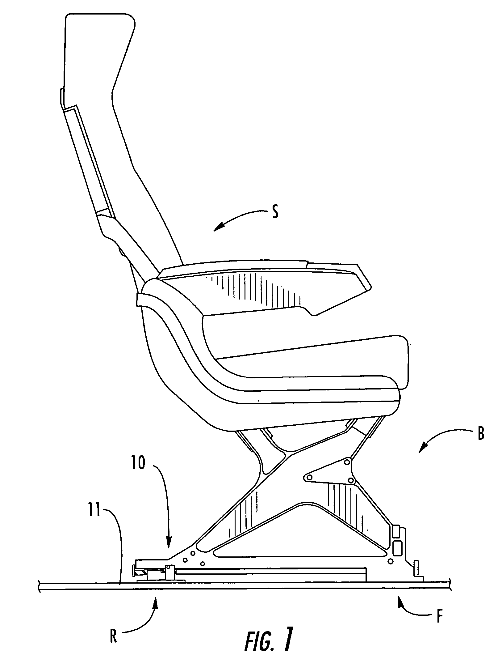
[0049]Referring now specifically to the drawings wherein identical reference numerals denote the same elements throughout the various views, a typical seating arrangement using the track fastener assembly and track fastener assembly according to the present invention is illustrated in FIG. 1. A seating unit “S” having a base frame “B” is positioned on a locking track 11 and locked thereto by means of a track fastener assembly 10 having a rear portion “R” and a forward portion “F”.

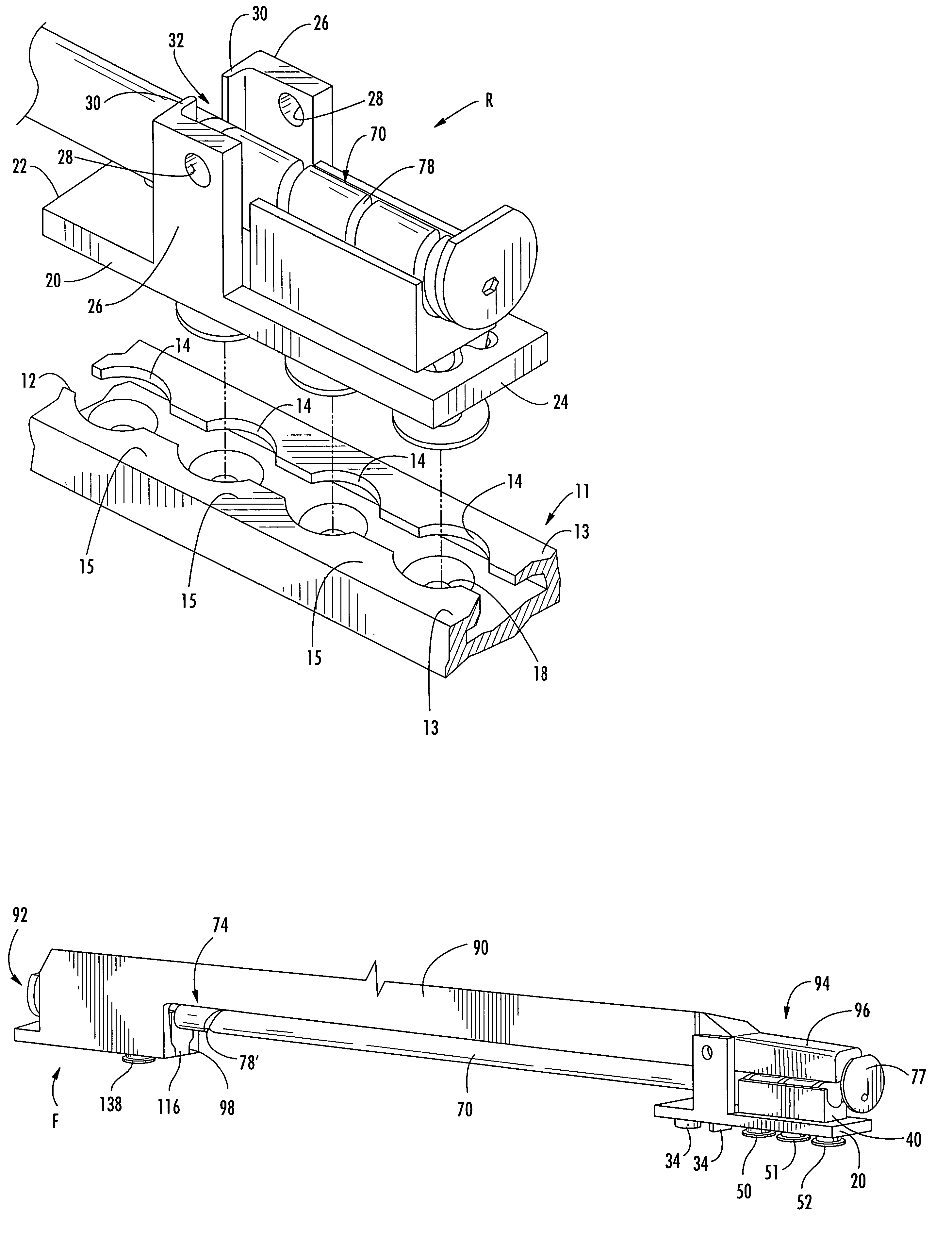
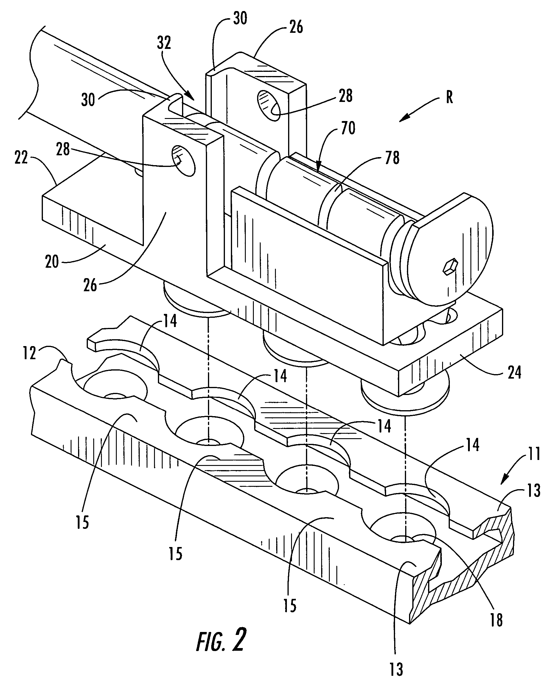
[0050]Referring now to FIG. 2, locking track 11 has a longitudinally-extending slot 12 therein which extends along the entire length of the locking track 11. Upper walls 13 of the locking track 11 define the slot 12 having regularly spaced-apart enlarged openings 14 along the length thereof, separated by relatively narrower track slot segments 15 which form the portions of the structure which actually perform the locking function. In FIG. 2 it is evident that the narrow track slot segments 15 extend into th...


PUM


Abstract

A track fastener assembly for securing a seat or cargo apparatus to a floor track of a vehicle. The assembly includes a bottom rail with forward and aft ends. Front and rear movable slides carrying locking studs are carried by the bottom rail. A locking rod having a helical groove formed in its outer surface is operatively connected to the bottom rail and the slides. Rotation of the locking rod causes the slides to move axially from an installation position to a locking position. As the slides move to the locking position, they are deflected upwards along with the attached locking studs, clamping the track fastener assembly to the track.

Description

[0001]This application is a continuation-in-part of application 10 / 779,061 filed on Feb. 13, 2004 and issued as U.S. Pat. No. 6,902,365 on Jun. 7, 2005.TECHNICAL FIELD AND BACKGROUND OF THE INVENTION[0002]This invention relates to a track fastener assembly of the type used to anchor seats or cargo to tracks fitted to the floor of a vehicle. The particular embodiment disclosed herein is of a track fastener assembly for securing an aircraft passenger seating unit to the floor of an aircraft. Therefore the vehicle referred to throughout this application is an aircraft. It is understood that the invention relates as well to other types of vehicles such as trains, buses or the like.[0003]Many aircraft require the capability to be differently configured to meet varying cargo and / or passenger-carrying requirements such as the removal or addition of passenger seats and / or cargo. In addition, aircraft also must have the capability to easily and quickly relocate or reposition seats and / or car...

Claims


Application Information

Patent Timeline
Patent Type & Authority Patents(United States)
IPC IPC(8): B60P7/08B61D45/00B64D11/06
CPCB64D11/0696Y02T50/46B61D33/00Y02T50/40
Inventor DOWTY, MARK BRIAN
Owner BE AEROSPACE INCORPORATED
Why Eureka
Try Eureka