Yoke bearing providing improved support

a technology of yoke bearing and support rod, which is applied in the direction of gearing, lifting equipment, transportation and packaging, etc., can solve the problems of increased friction between the rack and the yoke bearing, large separation force, and large spring force to press the yoke bearing

Inactive Publication Date: 2006-04-25
TEDRIVE HLDG
View PDF19 Cites 5 Cited by
  • Summary
  • Abstract
  • Description
  • Claims
  • Application Information

AI Technical Summary

Benefits of technology

[0008]According to more detailed aspects, the deformable member is preferably an elastomeric ring, and most preferably a series of axially spaced elastomeric rings. Alternatively, the deformable member may comprise a she

Problems solved by technology

Unfortunately, as higher and higher pinion torque is generated, which is especially the case with pinions driven by an electric motor, large separation forces are generated.
Thus, large spring forces are required to press the yoke and yoke bearing against the rack.
However, higher spring forces result in increased friction between the rack and th

Method used


Image

  • Yoke bearing providing improved support
  • Yoke bearing providing improved support
  • Yoke bearing providing improved support

Examples


Embodiment Construction

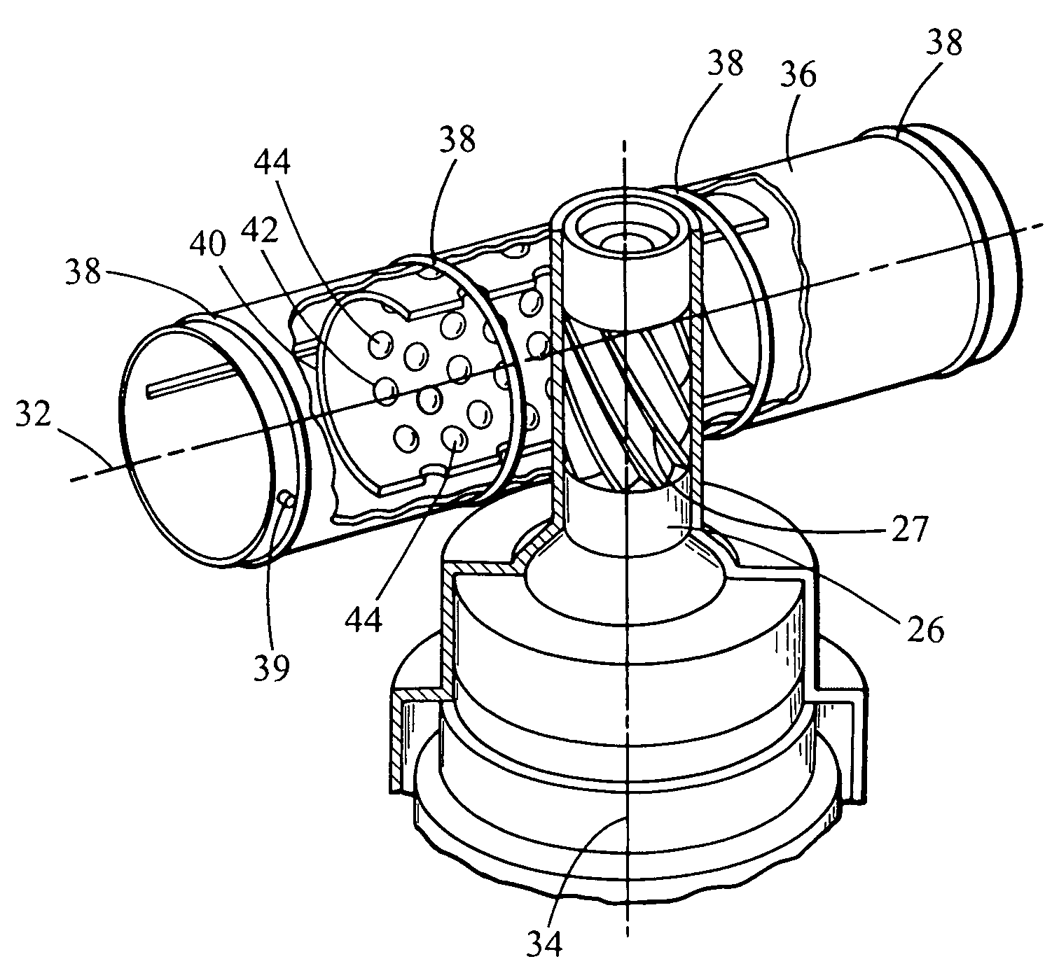
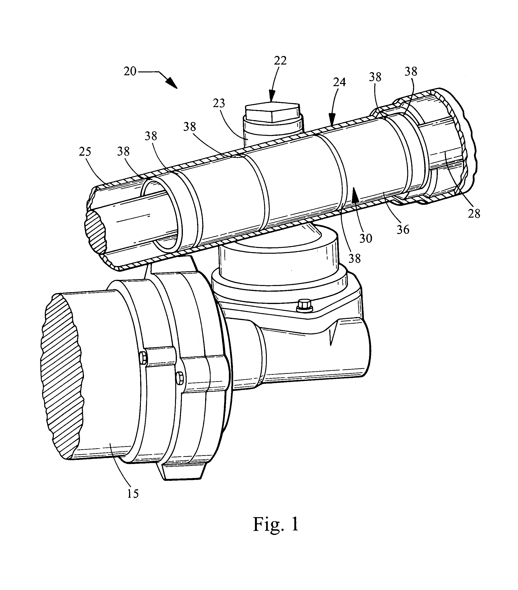
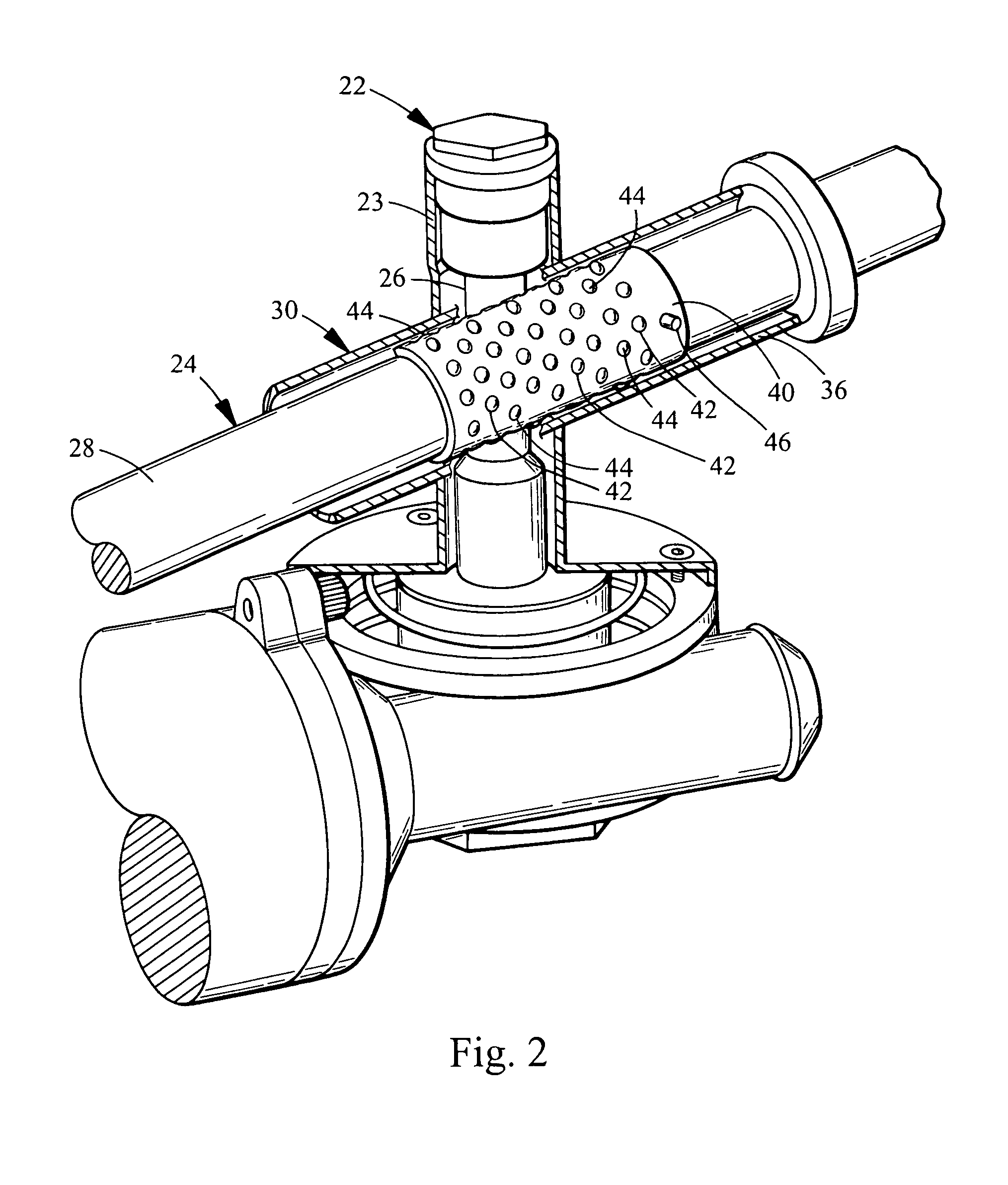
[0015]Turning now to the figures, FIG. 1 is a perspective view of a steering gear assembly 20 constructed in accordance with the teachings of the present invention. The steering gear assembly 20 generally includes a pinion 22 operatively connected to a rack 24. The pinion 22 generally includes a pinion housing 23 substantially enclosing a pinion gear 26 (FIGS. 2 and 3). The pinion gear 26 includes teeth 27 (FIG. 3) which is driving engagement with the rack 24. The rack 24 generally includes a housing 25 which substantially encloses a rack gear 28. The rack gear 28 is linearly translated by virtue of its engagement with the pinion gear 26, as is well understood in the art. A bearing assembly 30 engages the rack 24 and biases the same into the pinion 22 to provide reliable engagement of the rack 24 and pinion 22.

[0016]Uniquely, the bearing assembly 30 of the present invention provides improved support to the rack 24. Not only does the bearing assembly 30 provide increased support alon...


PUM


Abstract

A steering gear assembly includes a pinion defining a pinion axis and a rack defining a rack axis. A bearing assembly includes a roller bearing biased against the rack to generate a normal force pressing the rack into engagement with the pinion. The bearing assembly engages an outer surface of the rack at two points circumferentially spanning a large angle to provide improved support. The roller bearing is preferably a plurality of ball bearings engaging an outer race. A deformable member may be utilized that is positioned between the outer race and the rack housing. The deformable member may comprise a series of O-rings which providing a force biasing the outer race towards the pinion.

Description

FIELD OF THE INVENTION[0001]The present invention relates generally to steering gear assemblies having a rack and pinion, and more particularly relates to yoke bearings supporting engagement of the rack and pinion.BACKGROUND OF THE INVENTION[0002]A steering gear assembly typically comprises a rack and pinion gear system that translates the rotational movement of the pinion into linear movement of the rack. Many modern vehicles include electric power assisted steering, and these gear assemblies utilize dual pinions. One pinion is responsive to steering wheel input, while the other pinion is powered by an electric motor to provide steering assistance or other controlled steering operations.[0003]When the pinions are subject to high torques or quick changes in torque direction, separation forces are generated between the rack and pinion gears. Accordingly, a yoke assembly is typically provided to keep the rack and pinion in engagement. The yoke assembly typically includes a slide beari...

Claims


Application Information

Patent Timeline
IPC IPC(8): F16H1/04B62D3/12F16C25/08F16C29/04F16C29/12F16H55/28
CPCB62D3/123F16C29/04F16C29/123F16H55/283Y10T74/18088F16H55/285Y10T74/1967Y10T74/19623
Inventor ROBERTSON, JAMESPALAKODATI, SUNILFOWLKES, EDWARDYANOSEK, MATTHEW
Owner TEDRIVE HLDG
Why Eureka
Try Eureka