Coordinate input apparatus
a technology of input apparatus and input data, which is applied in the field of coordinate input apparatus, can solve the problems of high cost of detectors, high cost, and large amount of power consumption, and achieve the effects of low cost, high accuracy and small input of coordinates
- Summary
- Abstract
- Description
- Claims
- Application Information
AI Technical Summary
Benefits of technology
Problems solved by technology
Method used
Image

Examples
first embodiment
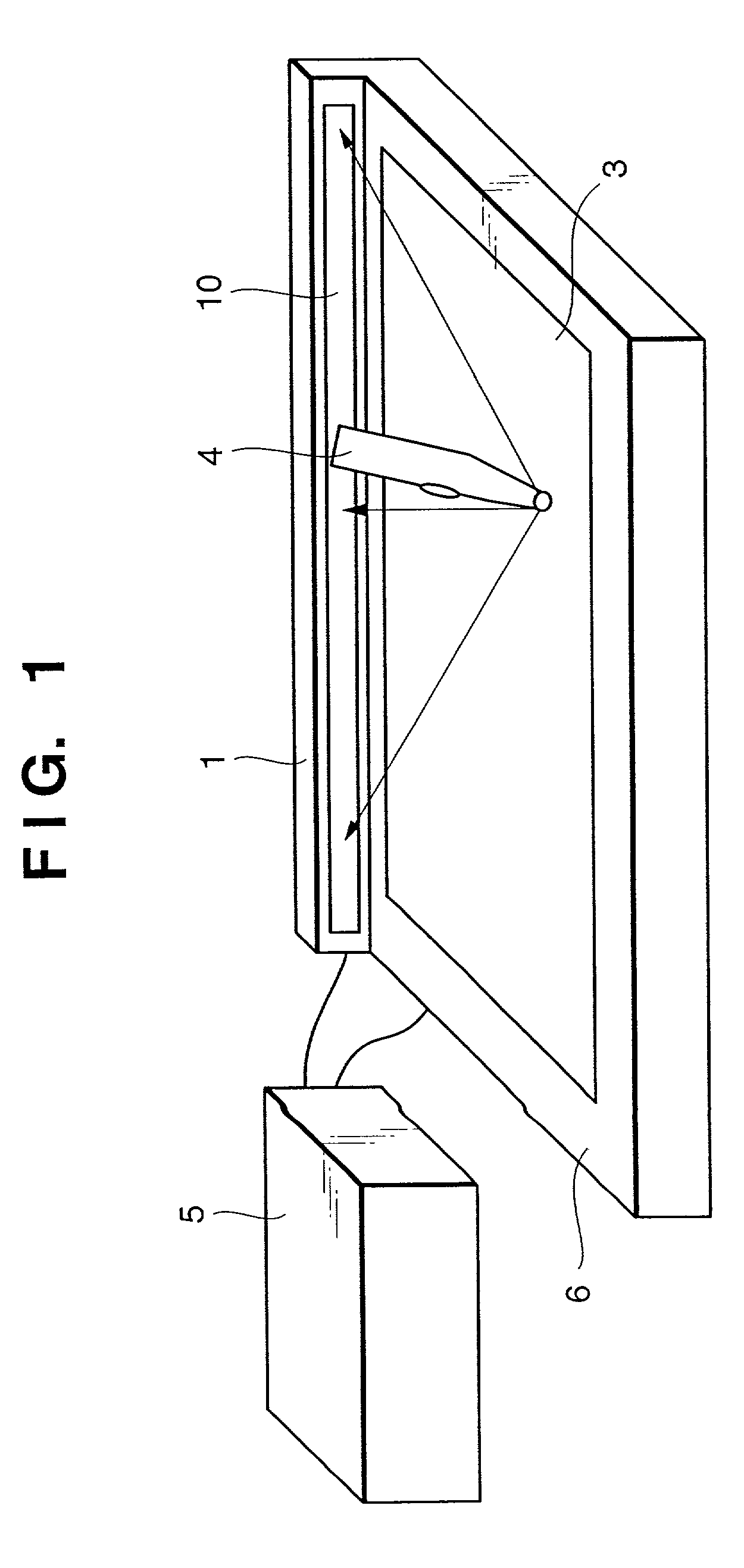
[0025]FIG. 1 is a perspective view schematically illustrating a coordinate input apparatus according to the present invention.
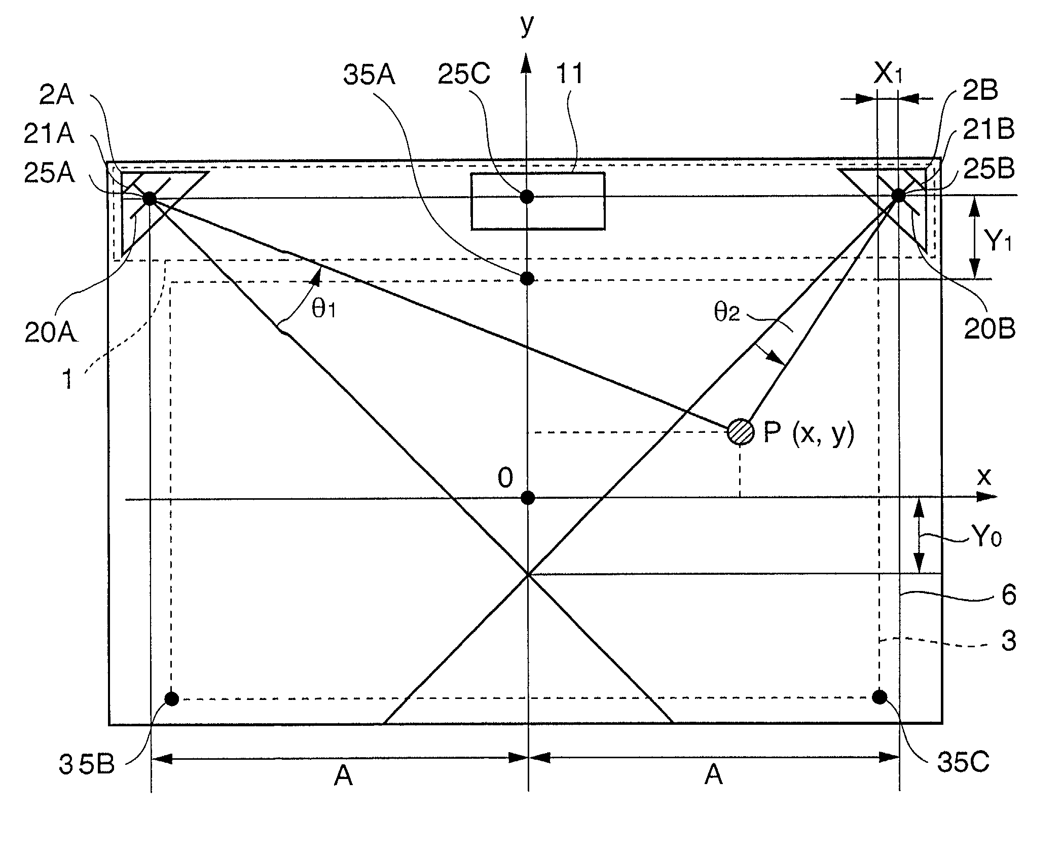
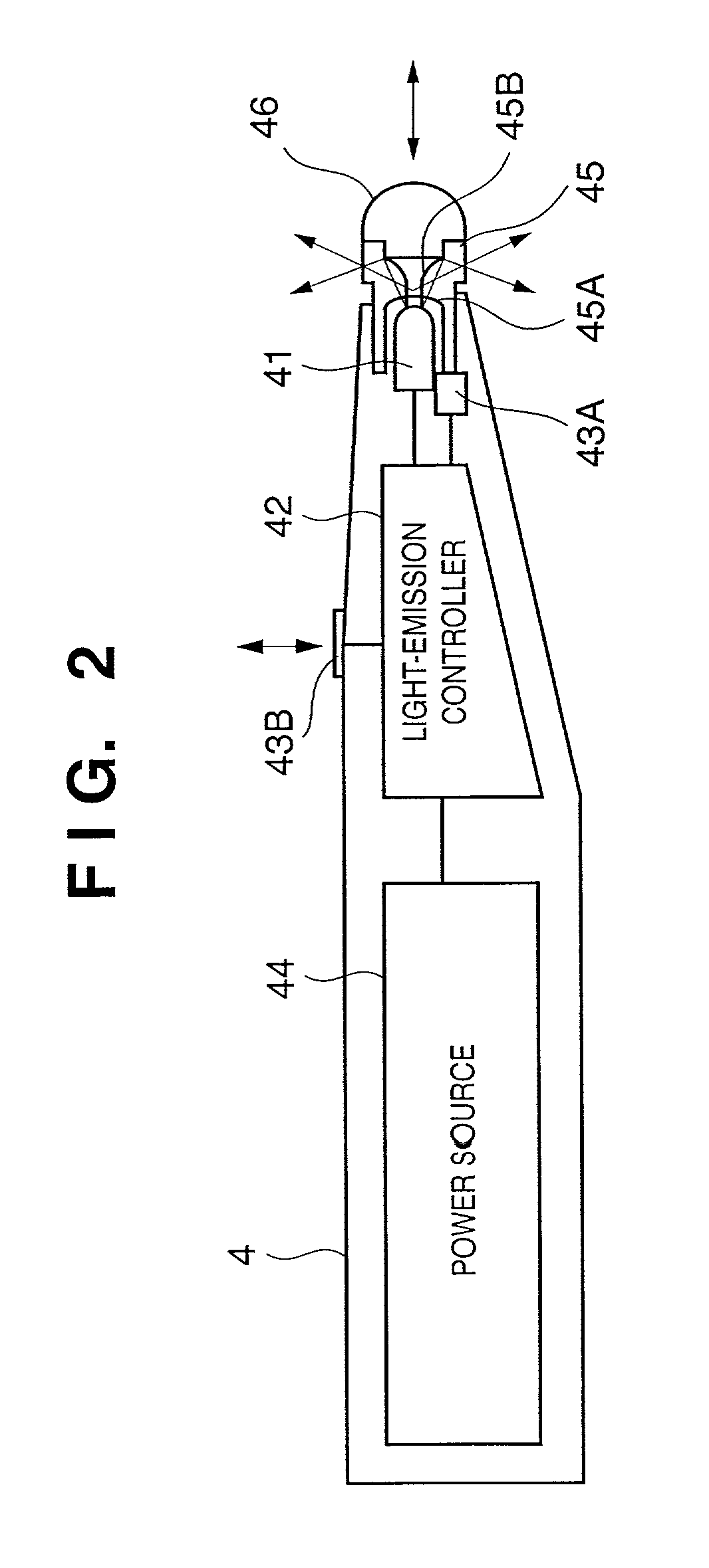
[0026]Broadly speaking, the coordinate input apparatus according to this embodiment comprises a designating tool 4 the tip of which is provided with a light-emitting portion for generating diffused light, and a coordinate detection unit 1 for detecting coordinates of the position of the light-emitting portion of the designating tool 4 in response to operation of the designating tool 4 within a coordinate input zone 3, which is a rectangular plane.
[0027]Also shown in FIG. 1 are a computer 5 connected to the coordinate detection unit 1 and, as an output device, a flat-panel display unit 6 for displaying images or the above-mentioned position information, etc., using the coordinate input zone 3 as a display area.
[0028]The computer 5 is a general-purpose computer having a CPU, a RAM, a ROM, a hard disk, an external storage device, a network interface, a display, ...
second embodiment
[0083]However, if Y1 is much larger than 113 mm, spacing the coordinate detection unit 1 away from the coordinate input zone 3 by this amount will result in a coordinate input apparatus of large size and will detract from the appearance of the apparatus. In the second embodiment, therefore, the optical path is bent at a right angle by a mirror 12 and the thickness of the flat-panel display unit 6 is utilized to reduce the external dimensions of the apparatus. More specifically, the mirror 12 is placed in the vicinity of one side of the coordinate input zone 3 on the side near the midpoint 25C of the line segment connecting the fiducial points 25A, 25B, and the angle detectors 2A, 2B are placed toward the rear or front of the input surface or on the back side thereof.
[0084]The angle of the mirror 12 and the number of reflections can be decided based upon the particular design. Further, the type of mirror used will differ depending upon the structure and thickness of the flat-panel di...
third embodiment
[0088]FIG. 10 is a side view illustrating the optical path of the angle detector 2A′ according to the
[0089]In a manner similar to the angle detector 2A described in the first embodiment, the angle detector 2A′ of this embodiment is provided with the mirror 24A, slit 20A and linear sensor 21A for performing detection over an angular range of about 90° and, on the opposite side, a mirror 24C, slit 20C and linear sensor 21C for performing detection over an angular range of about 30°. The distance between the slit 20C and linear sensor 21C is made about three times the distance between the slit 20A and linear sensor 21A. As a result, detection is performed at approximately three times the angular resolution. Further, the range of detection is limited to the portion near the upper side.
[0090]A changeover between the two linear sensors 21A and 21C may be performed at a predetermined angle, or a changeover range of a fixed width (e.g., 2°) may be set and the changeover may be made smoothly...
PUM
 Abstract
Description
Claims
Application Information
 - R&D Engineer
- R&D Manager
- IP Professional
- Industry Leading Data Capabilities
- Powerful AI technology
- Patent DNA Extraction
Browse by: Latest US Patents, China's latest patents, Technical Efficacy Thesaurus, Application Domain, Technology Topic.
© 2024 PatSnap. All rights reserved.Legal|Privacy policy|Modern Slavery Act Transparency Statement|Sitemap