Automatic DC bias control for the duobinary modulation format utilizing a low-pass electrical filter

a low-pass electrical filter and duobinary modulation technology, applied in the field of automatic dc bias control, can solve the problems of not meeting the requirements of the conventional abc circui

Active Publication Date: 2006-04-25
II VI DELAWARE INC
View PDF8 Cites 5 Cited by
  • Summary
  • Abstract
  • Description
  • Claims
  • Application Information

AI Technical Summary

Problems solved by technology

US-2004-0247324-A1, filed on even date herewith, which is incorporated herein in its entirety), however, the conditions that permit the use of the conventional ABC circuit are not met, and a new, more sophisticated ABC circuit is needed.

Method used


Image

  • Automatic DC bias control for the duobinary modulation format utilizing a low-pass electrical filter
  • Automatic DC bias control for the duobinary modulation format utilizing a low-pass electrical filter
  • Automatic DC bias control for the duobinary modulation format utilizing a low-pass electrical filter

Examples


Embodiment Construction

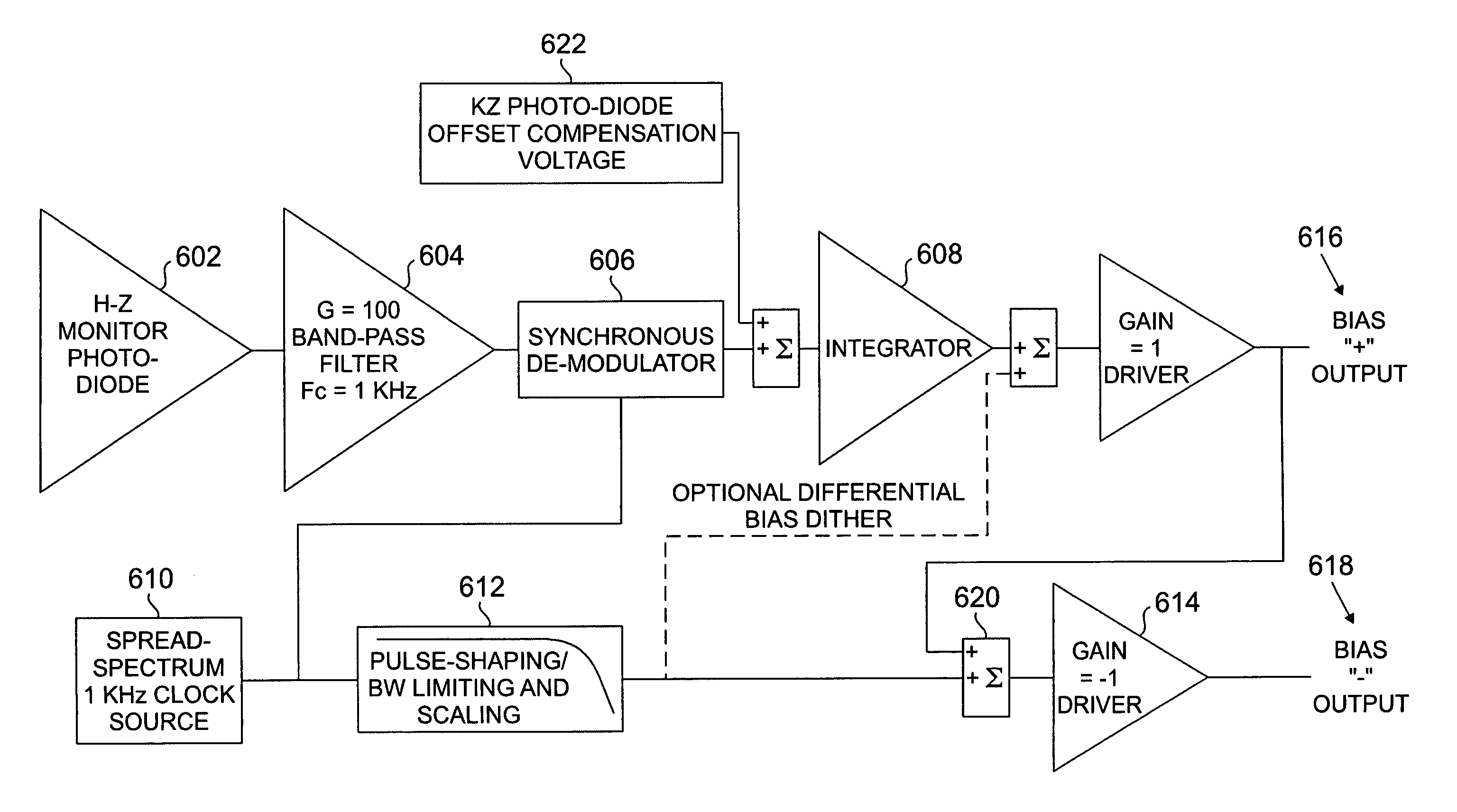
[0016]A duobinary ABC circuit is provided to control the bias point of the MZ modulator. In accordance with the present invention, a dither is applied to the DC bias of the modulator. The frequency of the dither is low, relative to the bit rate of the transmission. Light from the modulator is directed to a detector, where the component of the signal is measured that is synchronous with the dither. Maintaining this signal at a constant level ensures that the bias point of the modulator does not drift over time.

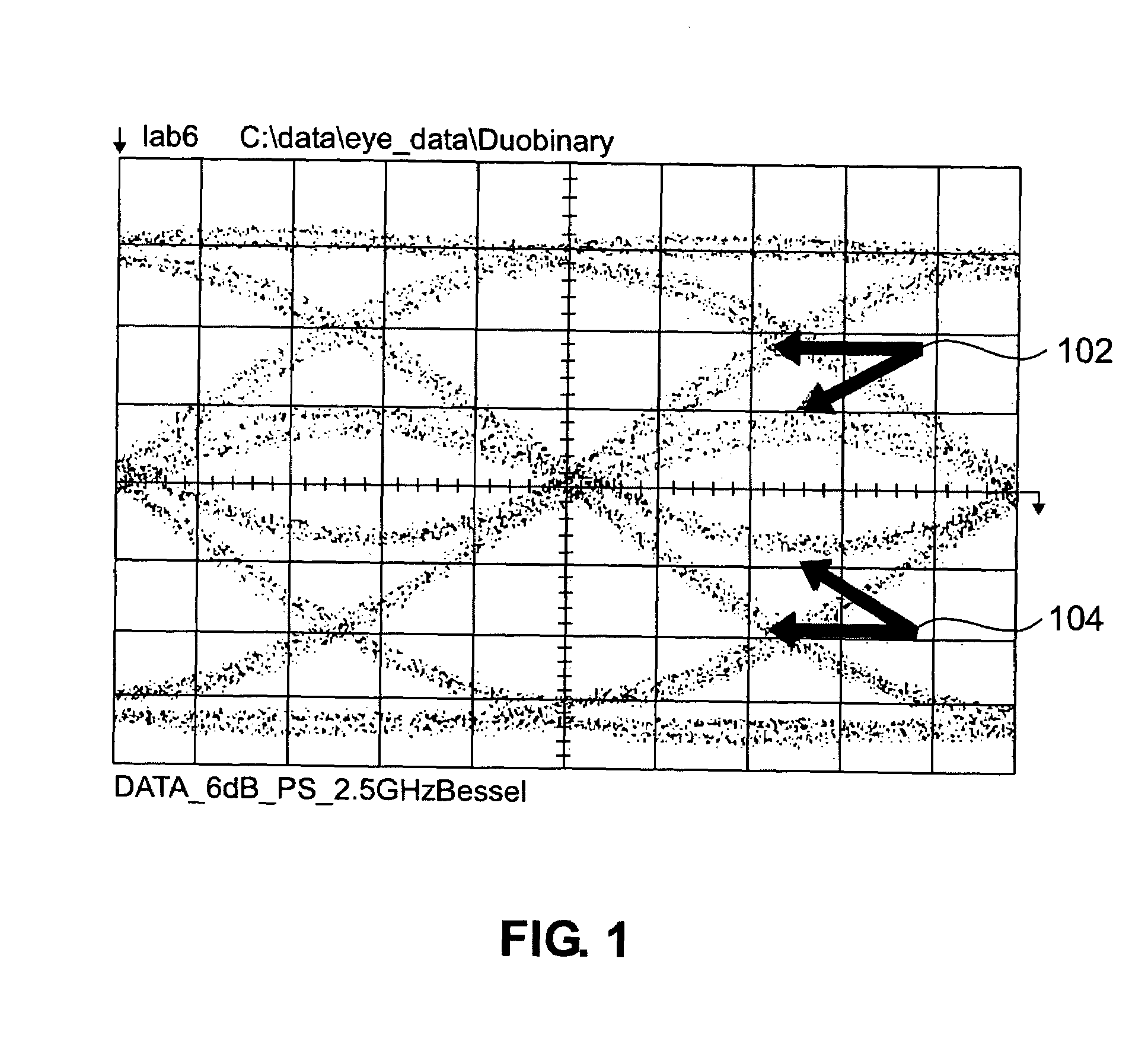
[0017]A duobinary modulation format utilizing low-pass electrical filtering of binary electrical signal presents specific set of problems for the automatic bias control of a LiNbO3 modulator. FIG. 1 shows a typical low-pass filtered electrical signal. This signal is converted into a phase difference using the electro-optic effect and then converted into amplitude modulation using a Mach-Zehnder structure. In FIG. 1 the electrical signal is shown at the output of low-pass electr...


PUM

PropertyMeasurementUnit
frequencyaaaaaaaaaa
spread-spectrumaaaaaaaaaa
phaseaaaaaaaaaa

Abstract

A method and apparatus is provided for controlling the bias point of a Mach-Zehnder modulator. The method begins by applying a dither signal to a DC bias that is applied to a Mach-Zehnder modulator. A component of an optical output signal provided by the Mach-Zehnder modulator that is synchronous with the dither signal is detected. The dither signal is adjusted to maintain the detected component of the optical output signal at a substantially constant value.

Description

STATEMENT OF RELATED APPLICATION[0001]This application claims the benefit of U.S. Provisional Patent Application Ser. No. 60 / 445,604, filed Feb. 7, 2003, and entitled “Duobinary Automatic Bias Control Circuit,” which is incorporated herein in its entirety.BACKGROUND OF THE INVENTION[0002]Mach-Zehnder modulators achieve amplitude modulation based upon the phase difference between two arms of Mach-Zehnder modulator being proportional to a difference in voltage signals applied to the two arms. The Mach-Zebnder structure allows for this phase modulation to be convened into amplitude modulation. When the input voltage signals are AC-coupled, a DC bias is required in order to set the operating point of the modulator. Due to physical processes in the modulator, the DC bias voltage required for proper operation is time-varying. In order to maintain the proper bias condition, a control circuit is needed that monitors the output of the modulator, and corrects for the time varying bias require...

Claims


Application Information

Patent Timeline
Patent Type & Authority Patents(United States)
IPC IPC(8): G02F1/01G02B26/00H04B10/07H04B10/516H04B10/524H04B10/54H04B10/61
CPCG02F1/0123G02F2201/126
Inventor HAREL, ROEYPAPPAS, DEANSHTENGEL, GLEBSTARK, JASON B.LE ROY, DONALD V.
Owner II VI DELAWARE INC
Why Eureka
Try Eureka