
Jewelry item

Inactive Publication Date: 2006-05-02
CHIA MEANG K +2
View PDF148 Cites 23 Cited by
  • Summary
  • Abstract
  • Description
  • Claims
  • Application Information

AI Technical Summary

Benefits of technology

[0065]It will be appreciated that, in accordance with the principles and concepts of the present invention, since the decorative object, decorative insert, or simulated decorative object or insert, is typically positioned below the top of the decorative jewelry item and above the bottom of the base member, snagging of clothing, and penetration of the user's skin is avoided. Unlike real gems, the simulated gem of the present invention does not extend below the bottom of the base member in which it is contained.
[0068]In the most preferred embodiments of the invention, the decorative insert or object is mounted within its single or multiple segmented base member with no part of the insert extending above the top rim, or bezel, of the base member. However, it will be understood that even if the decorative insert or object protrudes a small distance above the top rim, or bezel, clothing will not be snagged, and the slightly exposed top surface of the insert or object above the top rim, or bezel, will not be sufficient to scratch objects or the user's skin. If desired, in the manufacture of the decorative insert or object, a process step may be applied to round over, bevel, or otherwise soften the peripheral edges of the insert or object to assist in minimizing snagging of clothing or scratching objects or the user's skin. Accordingly, a secondary preferred embodiment of the invention will have the top surface of the decorative insert or object at the same level of, or slightly above, the top rim, or bezel, of the base member.

Problems solved by technology

Channel settings and bezel settings that use real gems increase the price of a jewelry item dramatically.
While this configuration displays the gem in the foreground relative to the setting, there are many disadvantages to such construction.
Moreover, the prongs of the setting base are unsightly, detracting from the aesthetic qualities of the item of jewelry.
If one were to conceive of the idea of avoiding the unsightliness of upwardly extending gem mounting prongs, the idea would be quickly rejected, due to the fact that if a precious stone, for example a diamond or ruby, is mounted below the upper surface of the setting base, the pointed bottom of the stone would penetrate the skin of the user even more so than is commonly done even with stones mounted from the top of a setting base or bezel.
Yet another disadvantage of the use of prior art unitary modules for connection in series to form a tennis bracelet, for example, is that such bracelet construction is rather labor intensive, each modular unit having to be connected to an adjacent unit, and for a bracelet with, typically thirty or more, individual modules, the cost of the bracelet to the ultimate consumer may be inflated beyond expectation of the purchaser who values the item of jewelry on the basis of its precious stone content.
Typical prong, channel, and bezel settings not only use expensive gems that sometimes get damaged during the setting procedure, but these types of settings themselves are costly.

Method used


Image

  • Jewelry item
  • Jewelry item
  • Jewelry item

Examples


Embodiment Construction

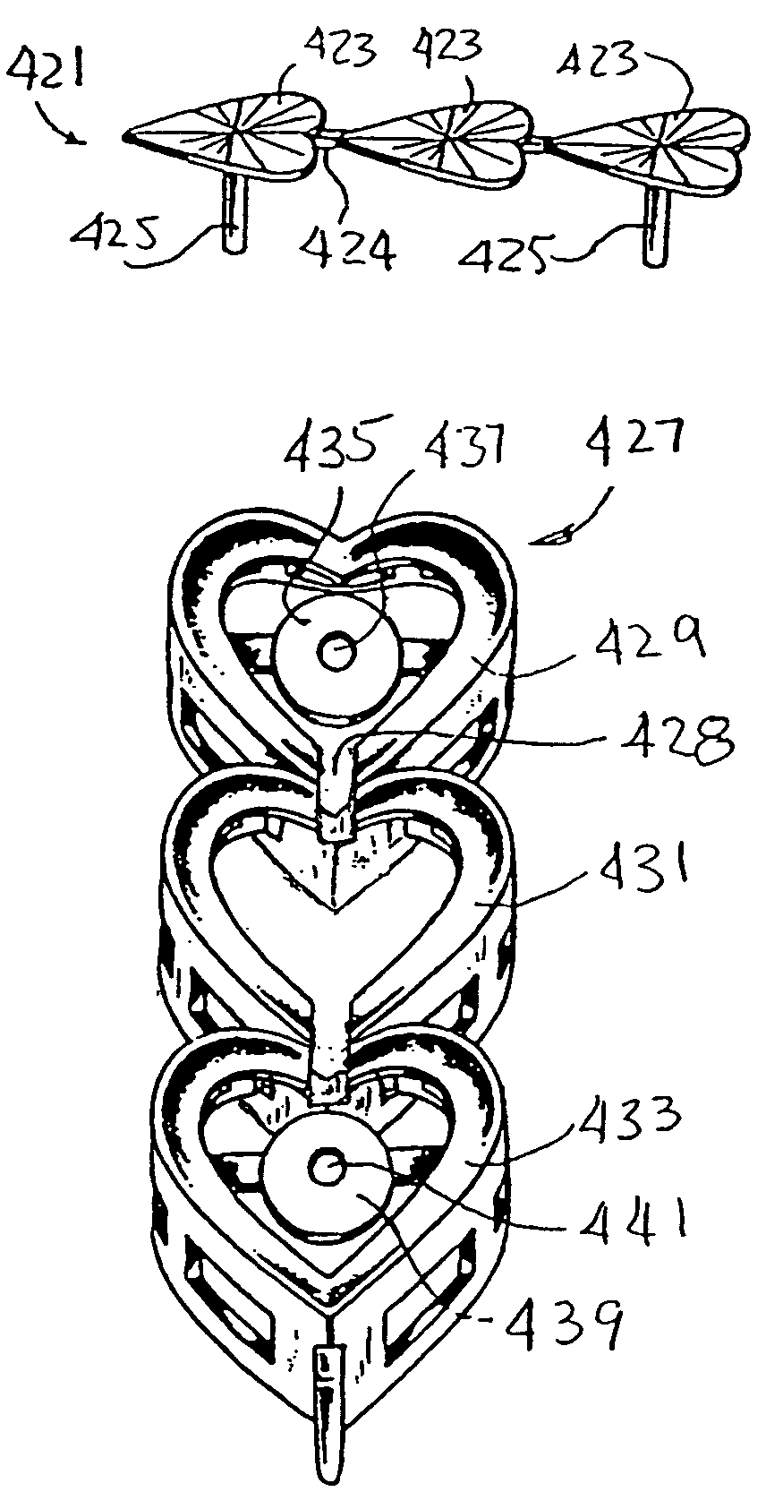
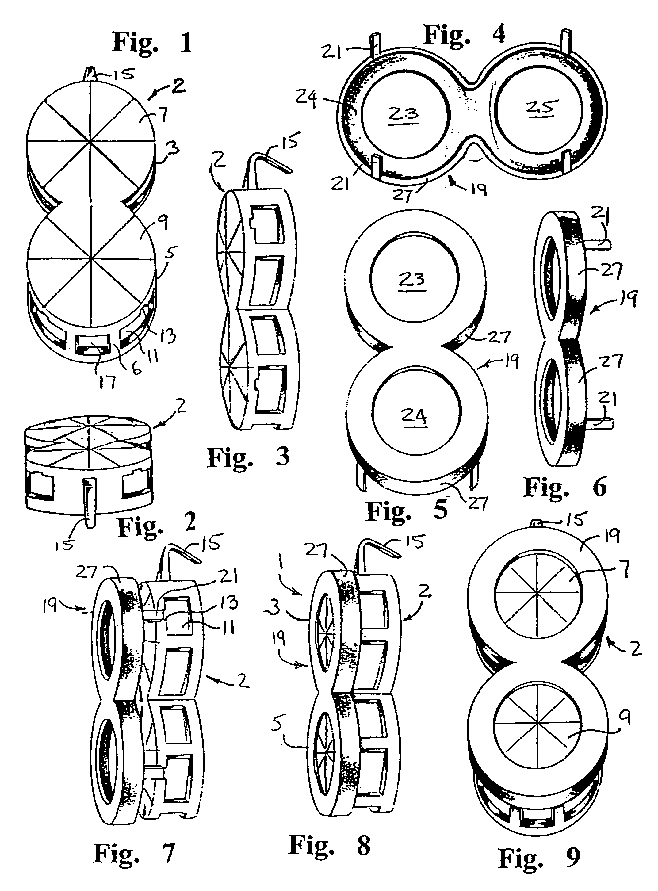
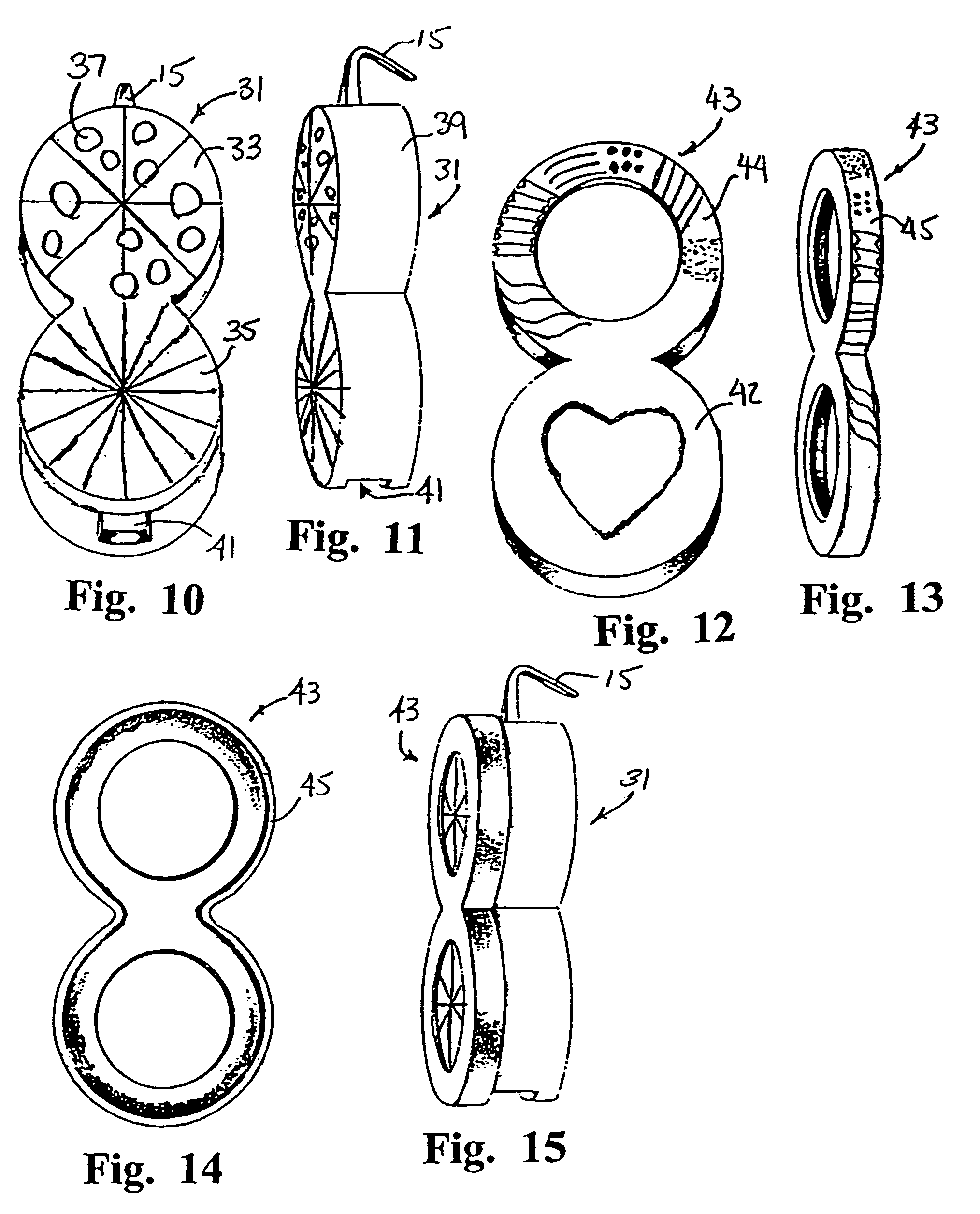
[0157]A first embodiment of the invention is shown in FIGS. 1–9. FIGS. 1–3 represent the front, rear, and side perspective views of the base member 2. In this embodiment, each decorative jewelry item 1 (FIG. 8), hereinafter also referred to as a module or modular link, is segmented to define two segments 3 and 5 in a substantially figure-8 shape. The dual segmented base member 1 has a segmented decorative top 7, 9, exhibiting a design representing a diamond cut surface on each segment. In the embodiment of FIGS. 1–9, the diamond cut design is formed integrally on the top surface of the base member 2. As will be described below, an alternate embodiment may employ a separate decorative object fixed to the top surface of the base member 2.

[0158]The base member 2 preferably has a hollow interior defined by a thin sidewall 6 extending downwardly from the decorative top 7, 9, the sidewall 6 having at least one cutout 13 extending through sidewall 6 into the interior of the base member 2.

[...


PUM

PropertyMeasurementUnit
Surfaceaaaaaaaaaa

Abstract

A decorative jewelry item comprises a base member (2) with a hollow interior and a decorative top (7), a cap (19) brought down over the decorative top, and a fastener arrangement (21) for fixing the cap to the base member after the cap is brought into contact with the decorative top. The cap has an opening (23, 25) therein through which the decorative top (7, 9) of the base member can be observed. All exposed surfaces of the base member (2) and cap (19) may have surface finishing features and / or graphic representations or designs to make the jewelry item more attractive. In an alternative construction, a decorative insert is inserted, through an opening in the top of a hollow base member, and is fixed within the base member with the insert below the base member top and viewable through the top opening. The jewelry item may be designed to have the appearance of a single decorative unit, or to have the appearance of a double (or greater) decorative unit. Such units have application in many jewelry items. A number of such units may be connected in series to form a tennis bracelet.

Description

[0001]This is a continuation-in-part application of: (1) U.S. patent application Ser. No. 09 / 383,814 (filed 26 Aug. 1999), now U.S. Pat. No. 6,532,766; (2) U.S. patent application Ser. No. 09 / 224,936 (filed 31 Dec. 1998), now abandoned; (3) U.S. Design Patent Application No. 29 / 120,104 (filed 10 Mar. 2000), now U.S. Design Pat. No. D453,122; (4) U.S. Design Patent Application No. 29 / 116,859 (filed 11 Jan. 2000), now U.S. Design Pat. No. D448,318; (5) U.S. Design Patent Application No. 29 / 110,327 (filed 3 Sep. 1999), now U.S. Design Pat. No. D471,129; and (6) U.S. Design Patent Application No. 29 / 098,058 (filed 21 Dec. 1998), now U.S. Design Pat. No. D418,445. All of the applications mentioned in the preceding sentence are incorporated herein by this reference.BACKGROUND OF THE INVENTION[0002]1. Field of the Invention[0003]This invention relates to items of jewelry, and in particular to a modular simulated gem and gem setting jewelry arrangement.[0004]2. Brief Description of the Art[...

Claims


Application Information

Patent Timeline
IPC IPC(8): A44C17/02A44C13/00
CPCA44C11/007Y10T29/23A44C17/02
Inventor CHIA, MEANG K.CHIA, CHEO K.CHIA, HUY K.
Owner CHIA MEANG K
Learn More