Self-priming centrifugal pump

a centrifugal pump and self-priming technology, applied in the direction of positive displacement liquid engines, gearing, non-positive displacement fluid engines, etc., can solve the problem of significantly reducing the efficiency of the pump

Active Publication Date: 2006-05-02
XYLEM IP HLDG
View PDF12 Cites 9 Cited by
  • Summary
  • Abstract
  • Description
  • Claims
  • Application Information

AI Technical Summary

Benefits of technology

[0015]A plurality of diaphragm drive elements can be provided, and a plurality of associated diaphragms can be mounted in a carrier, the carrier being mounted around the output shaft but not rotating with the output shaft. This arrangement enables a diaphragm carrier to be mounted around the output shaft at a fixed axial position. This makes sealing of the diaphragm carrier around the output shaft easier. The diaphragms can then be provided in a circle around the central axis, and they are controlled (synchronously) by the drive elements.
[0025]This arrangement enables an input shaft and an output shaft to be on the same axis, so that the arrangement takes up a minimum amount of space around the input and output shafts. Thus, a compact design is provided.

Problems solved by technology

There is still a need for a self-priming centrifugal pump in which the priming arrangement takes up a small amount of space and also does not reduce significantly the efficiency of the pump.

Method used


Image

  • Self-priming centrifugal pump
  • Self-priming centrifugal pump
  • Self-priming centrifugal pump

Examples


Embodiment Construction

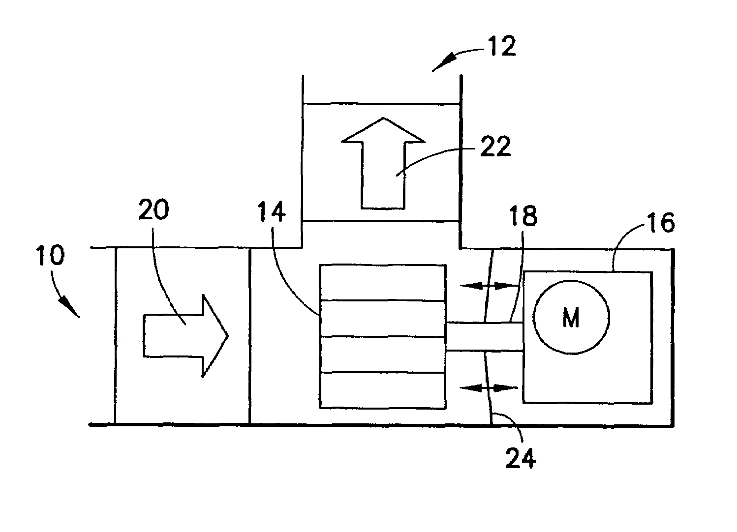
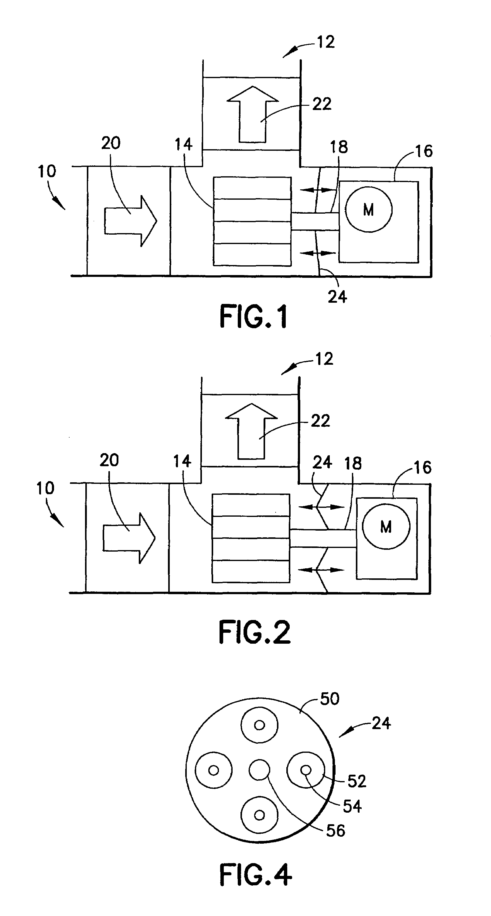
[0035]FIG. 1 shows schematically a first pump arrangement of the invention. The pump has an inlet 10 and an outlet 12, and a centrifugal impeller 14 for receiving liquid from the inlet and delivering it to the outlet. The impeller 14 is driven by a motor 16 about an output shaft 18 of the motor which is parallel to the direction of fluid intake. The fluid is expelled by the pump perpendicularly, in conventional manner.

[0036]In accordance with the invention, an inlet valve 20 and an outlet valve 22 are provided, and these cooperate with a diaphragm 24. The diaphragm 24 is driven by the motor 16 to provide priming and oscillates in reciprocal manner parallel to the shaft 18 to provide the priming operation. The diaphragm can be integrated into the housing without taking up significant additional space and uses relatively little power.

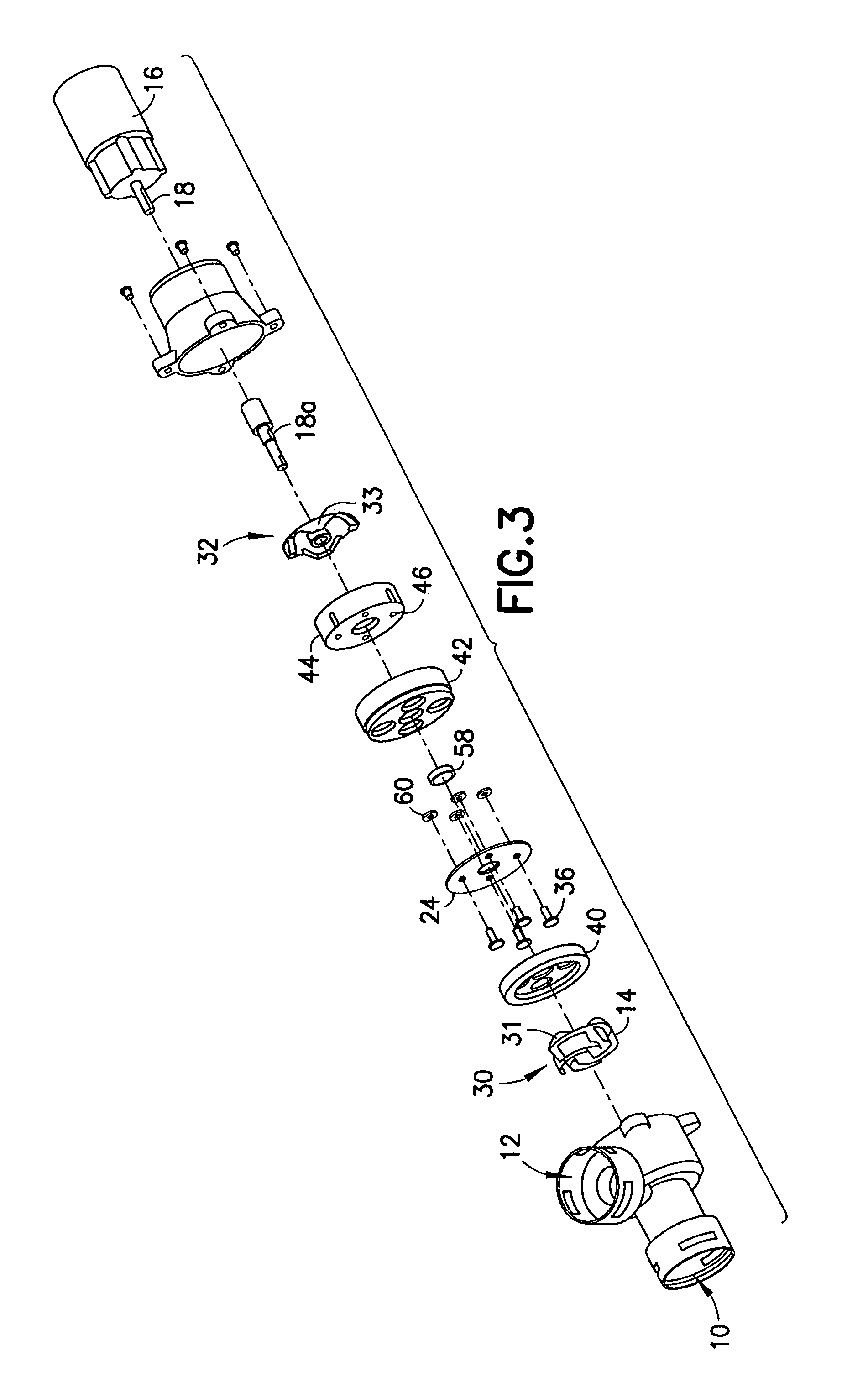
[0037]The pump includes an arrangement for converting rotation of the output shaft 18 into reciprocating movement for driving the diaphragm 24. This is n...


PUM


Abstract

A self-priming centrifugal pump comprises an inlet and an outlet, and a centrifugal impeller for receiving liquid from the inlet and delivering it to the outlet. An inlet valve and an outlet valve are provided, and a diaphragm arrangement is driven by the same motor as the impeller to provide priming. The diaphragm arrangement can be integrated into a pump design without taking up significant additional space. By driving the diaphragm arrangement with the motor, no additional power source is required.

Description

FIELD OF THE INVENTION[0001]The present invention relates to centrifugal pumps and more particularly to a self-priming centrifugal pump.BACKGROUND OF THE INVENTION[0002]A basic centrifugal pump is not self-priming, and various self-priming centrifugal pumps have been developed.[0003]Most commonly, a self-priming centrifugal pump is provided with a discharge tank contained in the pump housing and connected to recirculate liquid through the pumping chamber for priming. These tanks are initially provided with a supply of the liquid to be pumped and, during priming, the pump impeller is rotatably driven to recirculate liquid from the tank through the pumping chamber, so that gas in the pumping chamber becomes entrained with the recirculated liquid.[0004]In other designs, an additional external pump is provided simply for priming, for example a liquid piston pump functioning as a priming wheel.[0005]There is still a need for a self-priming centrifugal pump in which the priming arrangemen...

Claims


Application Information

Patent Timeline
Patent Type & Authority Patents(United States)
IPC IPC(8): F04B23/08F04D9/04
CPCF04D9/043F04D9/002F04D9/02F16H25/125
Inventor IRVINE, JAMES A.
Owner XYLEM IP HLDG
Why Eureka
Try Eureka