Transmit diversity gain for wireless communications networks

a wireless communication network and diversity gain technology, applied in multiplex communication, modulation, electromagnetic wave modulation, etc., can solve the problem of transmitter to two transmit antennas, and achieve the effect of increasing transmit diversity gain

Inactive Publication Date: 2006-05-02
MITSUBISHI ELECTRIC RES LAB INC
View PDF4 Cites 19 Cited by
  • Summary
  • Abstract
  • Description
  • Claims
  • Application Information

AI Technical Summary

Benefits of technology

[0011]A method and system increases transmit diversity gain in a wireless communication system. The system includes a transmitter with 2N transmit antennas, where N is greater than one, and a receiver with one or more receive antenna. The transmitter includes N stages connected serially to each other.

Problems solved by technology

However, the 3GPP W-CDMA standards for the STTD scheme limits the transmitter to two transmit antennas.

Method used


Image

  • Transmit diversity gain for wireless communications networks
  • Transmit diversity gain for wireless communications networks
  • Transmit diversity gain for wireless communications networks

Examples


Embodiment Construction

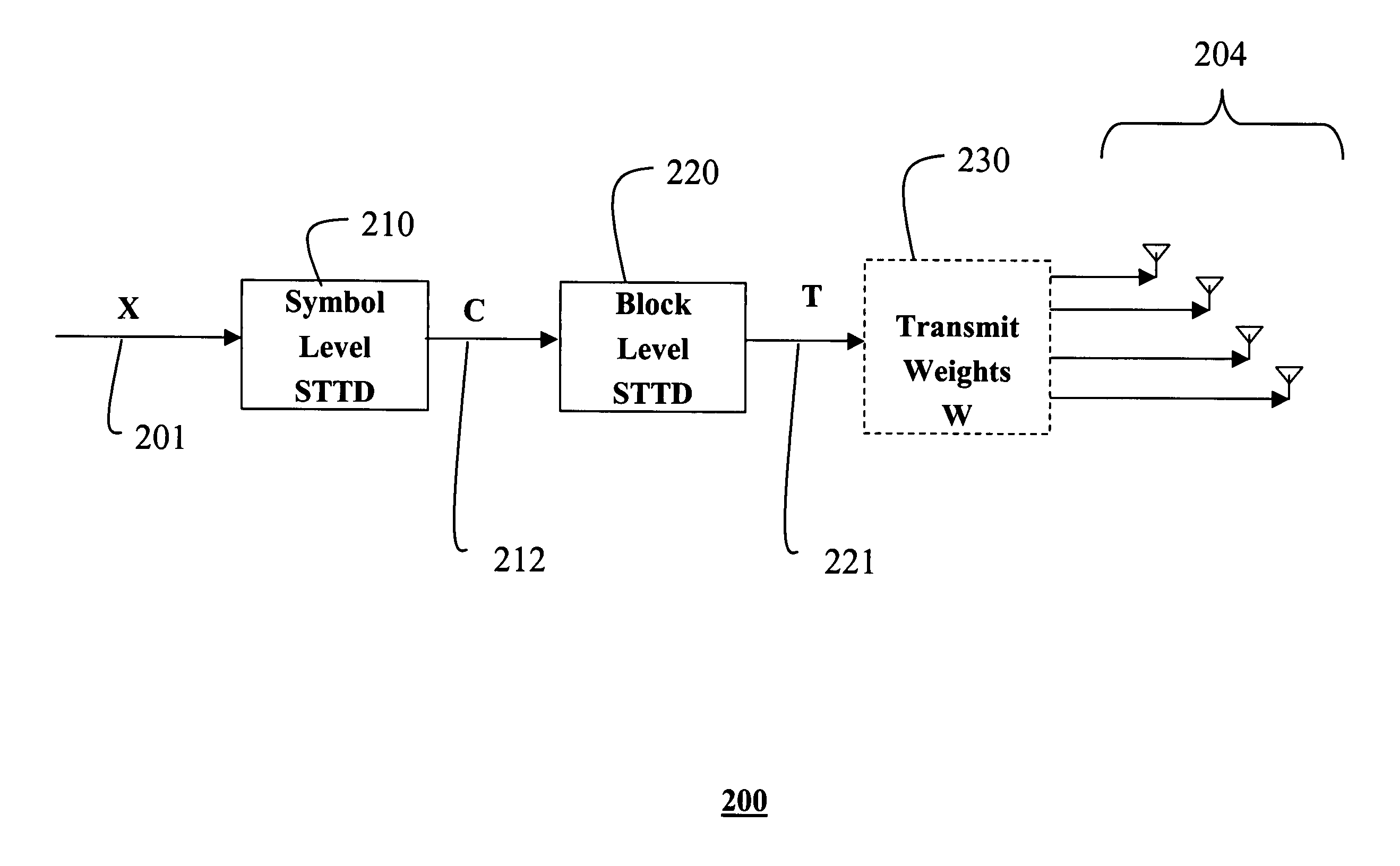
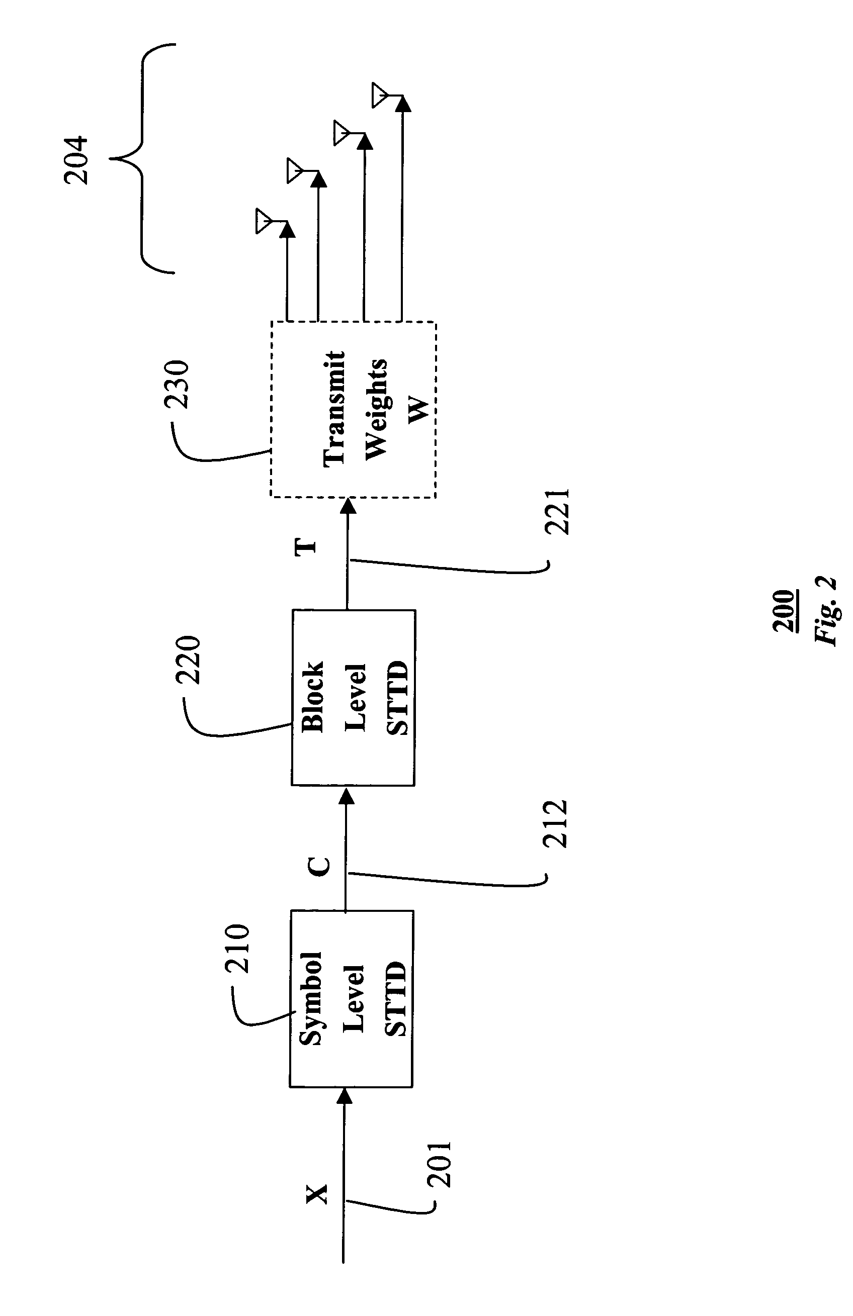
[0020]As shown in FIG. 2, the invention provides a transmitter 200 with 2N transmit antennas 201, where N is an integer value greater than one. This is an extension of the prior art STTD transmitter with two antennas, i.e. N equals one. For the example transmitter in FIG. 2, N equals two, so there are four transmit antennas 204.

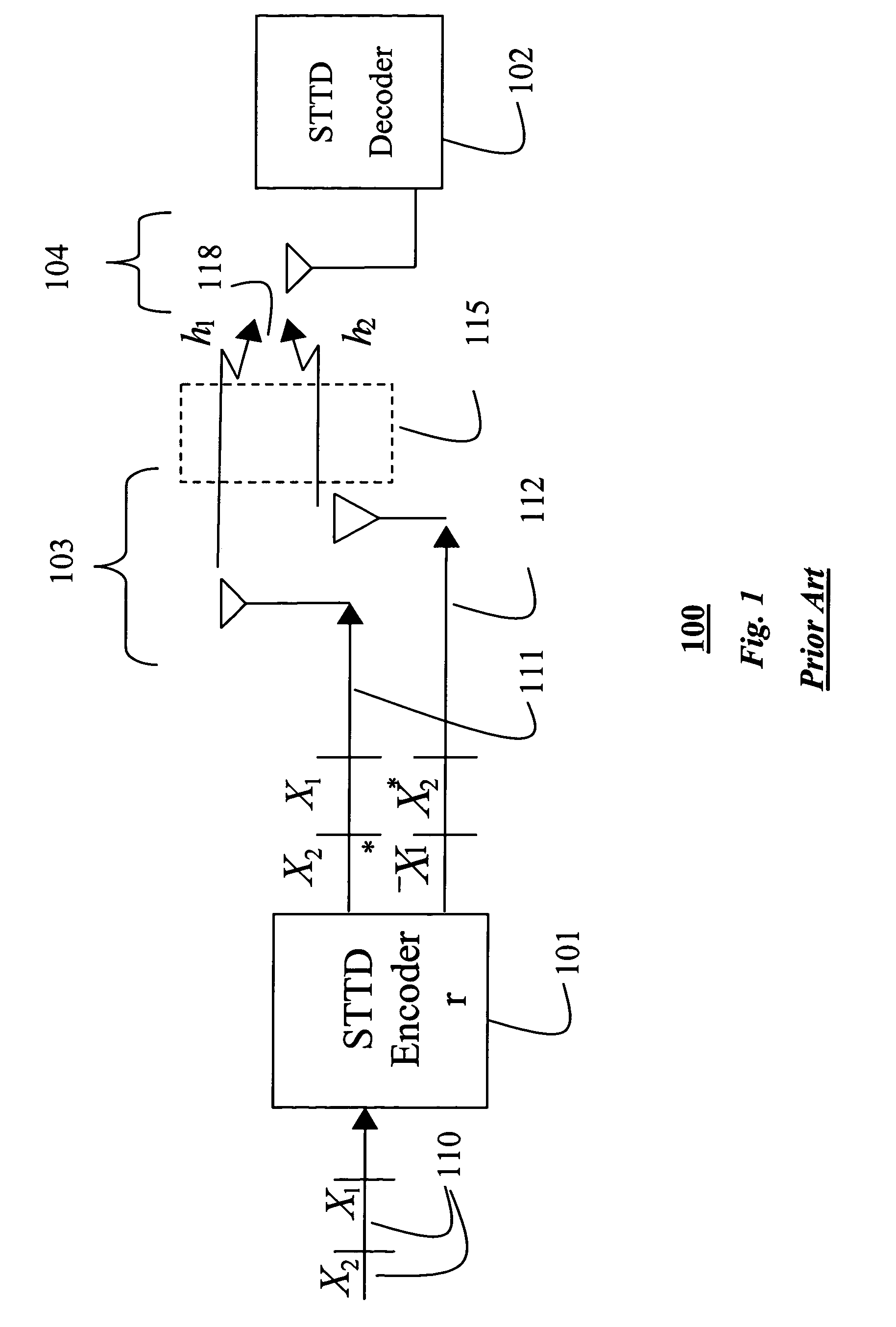
[0021]In order to be backward compatible with the prior art STTD system of FIG. 1, a transmit signal is generated as a stream of pairs of symbols. Each pair of symbols is denoted generally by X 110. Each pair of symbols is first encoded by a symbol level STTD encoder 210 as a matrix C 212 with two rows.

[0022]According to the invention, a pair of consecutive symbol pairs (X1, X2) and (X3, X4) encode 210 to a pair of matrices C1 and C2

[0023]C1=[X1X2X2*-X1*]⁢⁢and⁢⁢C2=[X3X4X4*-X3*].(2)

[0024]Next, a 4×4 matrix of transmit symbols T 221 are generated for the four antennas 204 from each pair of matrices C1 and C2 by a block level encoder 220. That is, each matrix C...


PUM


Abstract

A method and system that increases transmit diversity gain in a wireless communication system. The system includes a transmitter with 2N transmit antennas, where N is greater than one, and a receiver with one or more receive antenna. The transmitter includes N stages connected serially to each other. The first stage is a symbol level space-time transmit diversity encoder. Each of the next N−1 stages is a block level space-time transmit diversity encoder, for a total of N stages. The last stage is connected to the 2N antennas. The transmitter generates pairs of symbols in a form X1 and X2, The pairs of symbols are encoded by the first stage to produce a 21×21 output matrix C. Then, in each next block level stage n, the 2n−1×2n−1 output matrix of a previous stage is encoded to a 2n×2n output matrix, until a final output matrix has 2N rows of transmit symbols. The transmit symbols of the final output matrix are fed, in a left-to-right order, for each row, in a top-to-bottom order, to a corresponding different one of the 2N transmit antennas. A transmit weight is applied to each transmit symbol before transmitting the transmit symbol.

Description

FIELD OF THE INVENTION[0001]This invention relates generally to wireless communication networks, and more particularly to adaptive transmit diversity in such networks.BACKGROUND OF THE INVENTION[0002]Transmit diversity is one of the key technologies that define third generation wireless communication systems, such as cellular telephone networks. In such systems, spatial diversity is introduced into the signal by transmitting the signal through multiple antennas. Spatial diversity reduces the effects of channel fading by providing multiple independent copies of the signal at the receiver. With transmit diversity, the probability that all copies fade simultaneously in the channel is very small. As a result, the system performance is improved.[0003]Transmit diversity can use multiple spatially separated antennas, as well as various temporal or frequency modulation techniques, or combinations of these techniques.[0004]Space time transmit diversity (STTD) is an open loop transmit diversi...

Claims


Application Information

Patent Timeline
Patent Type & Authority Patents(United States)
IPC IPC(8): H04B1/02H04L27/04H03C7/02H04B1/707H04B7/02H04B7/06H04B7/26H04J13/00H04L1/06
CPCH04B7/0626H04L1/0625H04B7/0669
Inventor HORNG, JYHCHAU
Owner MITSUBISHI ELECTRIC RES LAB INC
Why Eureka
Try Eureka