Sewage effluent distribution means

a technology for distributing means and sewage effluent, which is applied in the direction of liquid displacement, sewage draining, separation processes, etc., can solve the problems of high maintenance and repair costs of sewage systems, and avoid or delay expensive maintenance costs

Active Publication Date: 2006-05-09
ZOOK NEAL
View PDF24 Cites 18 Cited by
  • Summary
  • Abstract
  • Description
  • Claims
  • Application Information

AI Technical Summary

Benefits of technology

[0009]The invention can thus provide a septic system in which effluent is uniformly distributed among the fingers of the drain field, thus avoiding or deferring expensive servicing of the septic system, and provides means for uniformly distributing effluent into a drain field that can easily be added to existing septic systems to avoid or defer such expensive servicing.

Problems solved by technology

Under such conditions, the soil affected by the portion of the drain field receiving effluent can become saturated, requiring service of the septic system and possibly modification of the drain field.
Because of the required excavation, re-installation of the distribution tank and the possible installation of new underground pipes, the servicing and modification of the sewage system can be expensive.

Method used


Image

  • Sewage effluent distribution means
  • Sewage effluent distribution means
  • Sewage effluent distribution means

Examples


Embodiment Construction

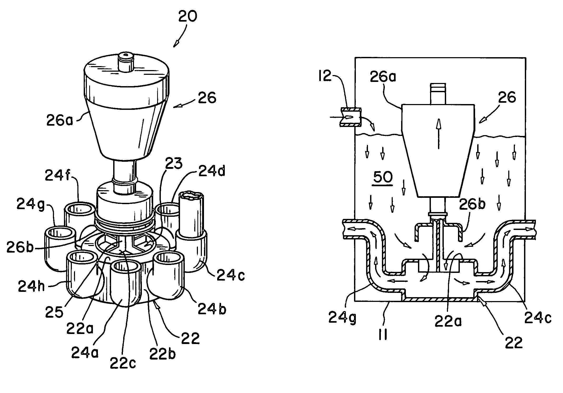
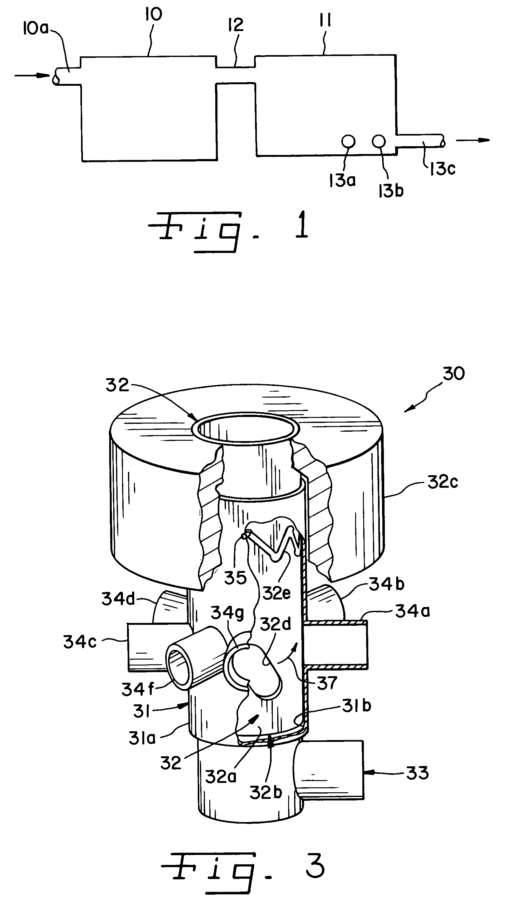
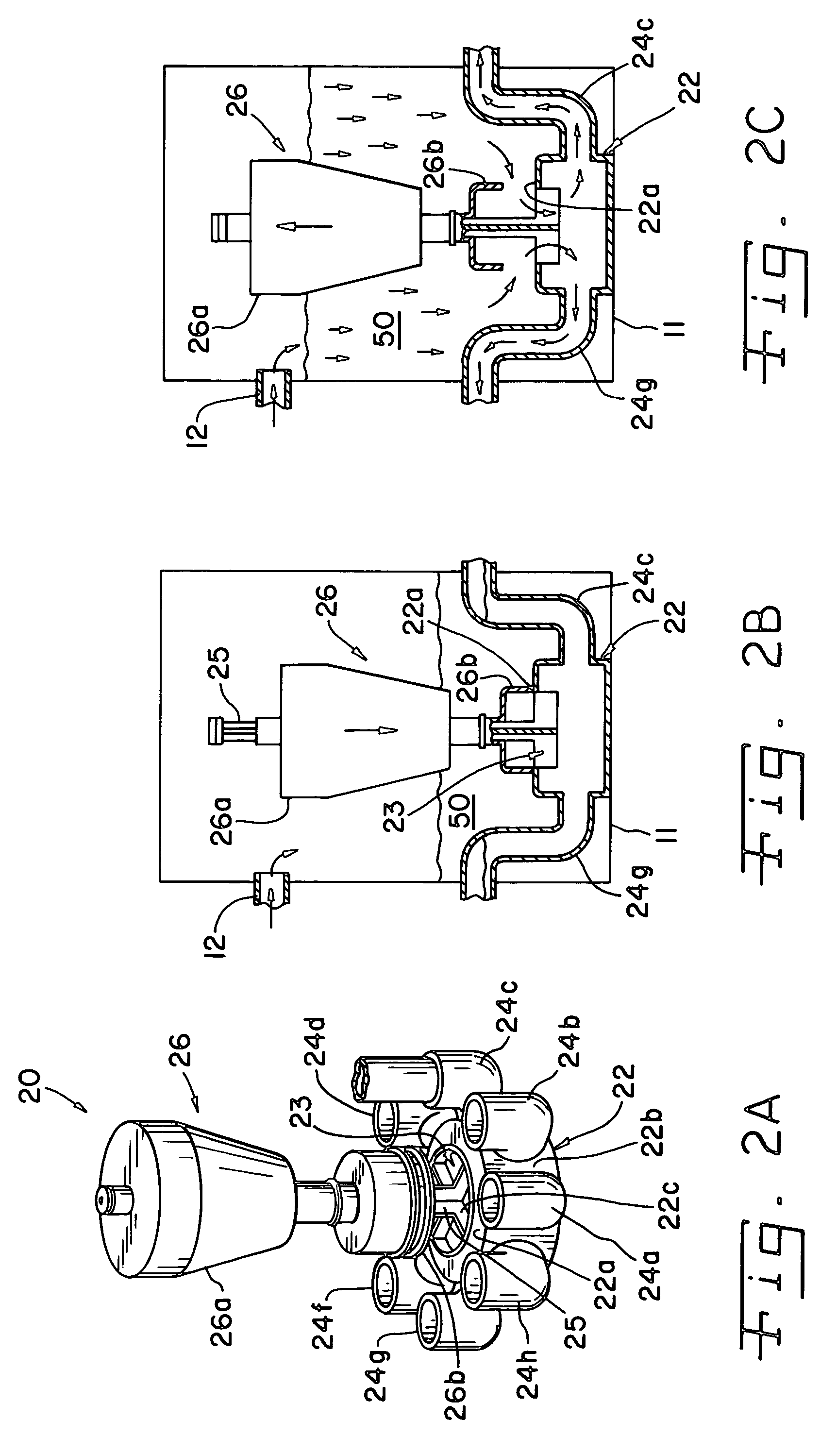
[0018]FIG. 1 is a diagram of a typical septic system. Such a system includes a septic tank 10 into which raw sewage is directed through an inlet 10a for treatment. In the septic collection tank 10, solid material and liquid material become segregated by virtue of their different densities, and the solid material is decomposed by the action of anaerobic bacteria. The resulting liquid sewage effluent flows from tank 10 to a distribution tank 11 through an interconnecting piping 12. In prior art systems, the distribution tank 10 includes a plurality of outlets 13a, 13b, 13c . . . 13x, each of which is connected to a different portion or finger of the drain field. In such systems, liquid effluent flows from the distribution tank 11 into the plurality of outlets 13a, 13b, 13c . . . 13x under the influence of gravity. If, however, the position of distributor box 11 shifts under the earth so that one or a few of the plurality of outlets, for example, outlet 13c shown in FIG. 1, is lower th...


PUM

PropertyMeasurementUnit
heightaaaaaaaaaa
heightaaaaaaaaaa
diameteraaaaaaaaaa

Abstract

Effluent-operated valves provide, in a septic system, distribution of effluent uniformly to a plurality of portions or fingers of a drain field. The installation of such valves in a tank that collects septic system effluent to be distributed to a plurality of fingers permits the uniform distribution of effluent from within the tank to a plurality of portions of a drain field, either simultaneously, or to one portion at a time in sequence.

Description

FIELD OF THE INVENTION[0001]This invention relates to septic systems for the treatment of sewage, and more particularly relates to systems for the distribution of the effluent of a septic system to a drain field, including a plurality of fingers.BACKGROUND OF THE INVENTION[0002]Septic systems are extensively used to treat sewage from individual residences and businesses in areas not served by sewers. In the treatment of sewage by such septic systems, solid and liquid waste from the residence or business is collected in a septic tank in which, because of their different densities, the solid and liquid components of the sewage separate. The solid material is decomposed within the tank by the action of anaerobic bacteria, resulting in a liquid effluent. The liquid effluent is then conveyed out of the tank and distributed through an area of subterranean soil, which is frequently referred to as a drain field, and the liquid effluent then percolates through the soil and becomes purified b...

Claims


Application Information

Patent Timeline
Patent Type & Authority Patents(United States)
IPC IPC(8): E02B11/00E03F1/00E03F11/00
CPCE03F1/002E03F11/00E03F2201/30Y10T137/7313
Inventor ZOOK, NEAL
Owner ZOOK NEAL
Why Eureka
Try Eureka