Sewage effluent distribution means

a technology for distributing means and sewage effluent, which is applied in the direction of sewage draining, separation processes, filtration separation, etc., can solve the problems of inconvenient servicing and modification of the sewage system, inability to uniformly flow effluent to the drain field, and inability to prevent effluent seepage, so as to avoid and defer expensive servicing, and rapid flow of effluen

Active Publication Date: 2010-01-07
ZOOK NEAL
View PDF27 Cites 8 Cited by
  • Summary
  • Abstract
  • Description
  • Claims
  • Application Information

AI Technical Summary

Benefits of technology

[0012]In an effluent distribution apparatus of the invention, such an effluent-operated valve can control and provide a rapid flow of effluent from a first effluent collection tank into a second distribution tank and simultaneously from the plurality of outlets formed in the second distribution tank to the plurality of portions or fingers in the drain field.
[0013]As the collected effluent leaves the effluent collection tank, the at least one buoyant member of the valve closure element reacts to the falling level of the effluent in the first container, or collection tank, and lowers the peripheral seal-forming surface at its bottom into sealing engagement with the valve outlet-forming and valve closure guiding element, permitting the accumulation of effluent in the effluent collection tank.
[0014]In preferred embodiments of effluent-operated valves of the invention, the buoyant member can be divided into an upper buoyant member and a lower buoyant member so the seal-forming surface of the valve closure assembly is supported above the cooperating seal-forming surface of the valve outlet for a longer period to allow more complete exhaustion of the effluent accumulated in the first collection tank.
[0015]In preferred embodiments of effluent-operated valves of the invention, magnetic attraction can be provided to assist in more positive seating of the seal-forming surface of the valve closure on the cooperating seal-forming surface of the valve outlet and prevent effluent seepage in the valve closure. For example, in a preferred embodiment of an effluent operated valve, the valve outlet-forming and valve closure guiding element carries a magnet, and the effluent-operated valve closure assembly carries an element that is attracted by the magnet as a peripheral seal-forming surface of the effluent-operated valve closure assembly approaches the peripheral sealable surface of the valve outlet-forming and valve closure guiding element.
[0016]The invention can thus provide a septic system apparatus by which effluent is more uniformly distributed among the fingers of a septic drain system, thus avoiding and deferring expensive servicing of the septic system, and provides means for uniformly distributing effluent into a drain field that can be easily added to existing septic systems to avoid and defer such expensive servicing.

Problems solved by technology

In addition, grease, mold, bacteria and other non-fluid waste can collect and grow in or on adjacent outlets of the distribution tank and restrict, and sometimes block, the flow of effluent from outlets of the distribution tank, creating a non uniform flow of effluent to the drain field.
Under such conditions, the soil affected by the portion of the drain field receiving excess effluent can become saturated, requiring service of the septic system and possibly modification of the drain field.
Because of the required excavation, re-installation of the distribution tank and the possible installation of new underground pipes, the servicing and modification of the sewage system can be expensive.

Method used


Image

  • Sewage effluent distribution means
  • Sewage effluent distribution means
  • Sewage effluent distribution means

Examples


Embodiment Construction

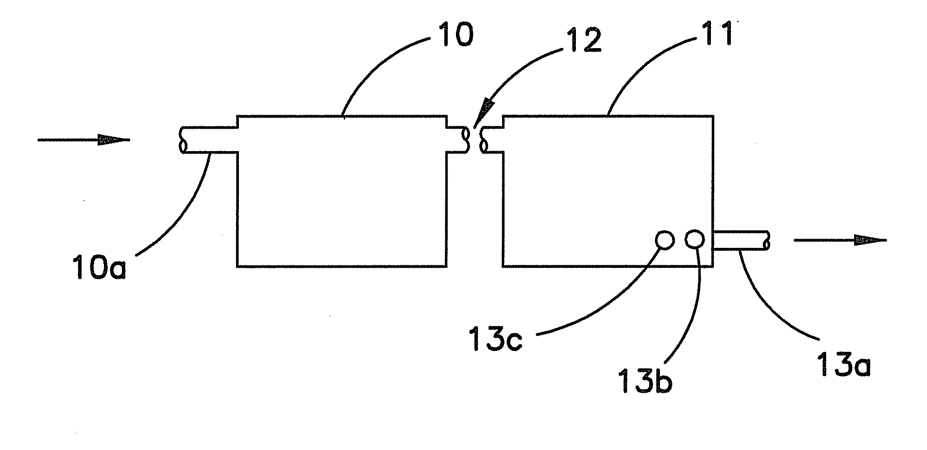
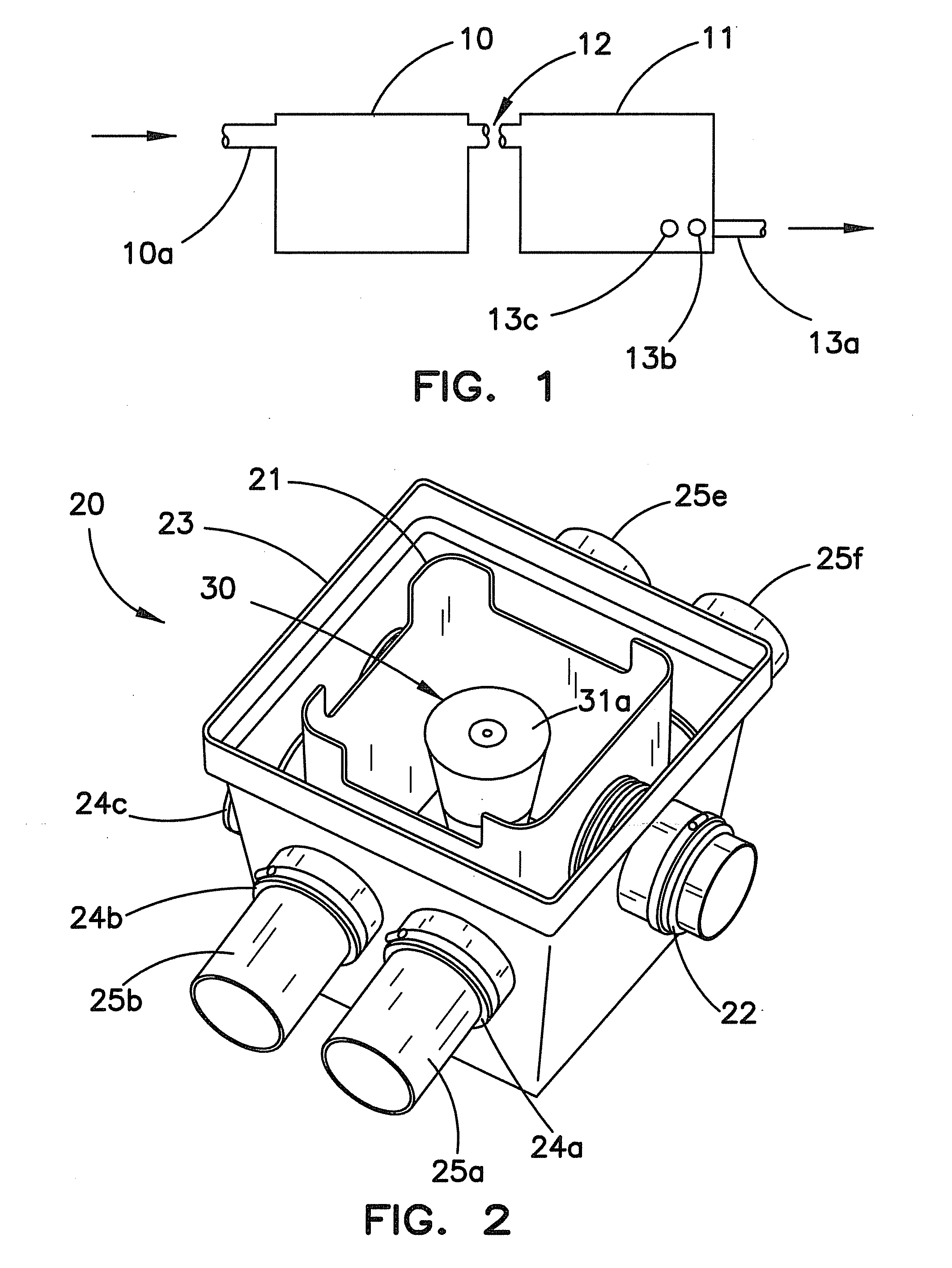
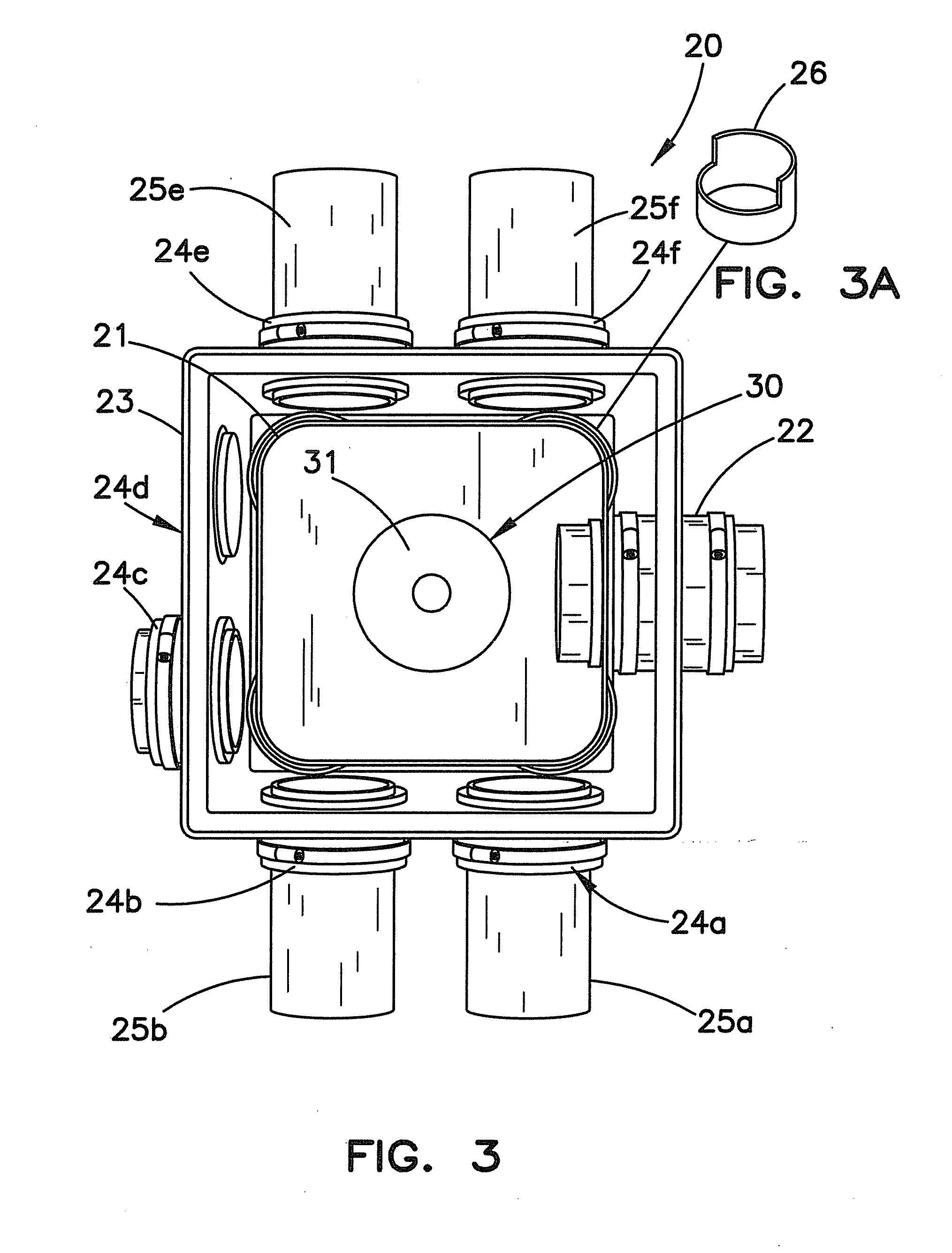
[0024]FIG. 1 is a diagram of a typical unimproved septic system. Such a system includes a septic tank 10 into which raw sewage is directed through an inlet 10a for treatment. In the septic tank 10, solid material and liquid material become segregated by virtue of their different densities, and the solid material is decomposed by the action of an anaerobic bacteria. The resulting liquid sewage effluent flows from tank 10 to a distribution tank 11 through interconnecting piping 12. The distribution tank 11 includes a plurality of outlets 13a, 13b, 13c . . . 13x, each of which is connected to a different portion or finger of the drain field. In such systems, the liquid effluent flows from the distribution tank 11 into the plurality of outlets 13a, 13b, 13c . . . 13x, under the influence of gravity. If, however, the position of the distribution tank 11 shifts under the earth so that one or a few of the plurality of outlets, for example, outlet 13a shown in FIG. 1, is lower than the othe...


PUM

PropertyMeasurementUnit
outer diameteraaaaaaaaaa
lengthaaaaaaaaaa
diameteraaaaaaaaaa

Abstract

A septic system can include an improved and more reliable apparatus for distributing effluent uniformly to a plurality of portions or fingers of a drain field. In such apparatus, an effluent container, or collection tank, is connected with the outlet of a septic tank, and an effluent-operated valve controls effluent flow from an outlet of the effluent container, or collection tank, to an effluent distribution tank which is connected to a plurality of portions, or fingers, of a sewage drain field to uniformly distribute the effluent from the septic tank to the drain field.

Description

[0001]This patent application claims the benefit under 35 U.S.C. 119(e) of U.S. Provisional Patent Application Ser. No. 61 / 077,217 filed Jul. 1, 2008.FIELD OF THE INVENTION[0002]This invention relates to septic systems for the treatment of sewage, and more particularly relates to systems for the distribution of the effluent of a septic system to a drain field, including a plurality of fingers.BACKGROUND OF THE INVENTION[0003]Septic systems are extensively used to treat sewage from individual residences and businesses in areas not served by sewers. In the treatment of sewage by such septic systems, solid and liquid waste from the residence or business is collected in a septic tank in which, because of their different densities, the solid and liquid components of the sewage separate. The solid material is decomposed within the tank by the action of anaerobic bacteria, resulting in a liquid effluent. The liquid effluent is then conveyed out of the tank and distributed through an area o...

Claims


Application Information

Patent Timeline
Patent Type & Authority Applications(United States)
IPC IPC(8): B01D21/34B01D35/157
CPCC02F1/006C02F3/288E03F1/002E02B13/02C02F2209/40Y10T137/7319Y10T137/7358
Inventor ZOOK, NEAL
Owner ZOOK NEAL
Why Eureka
Try Eureka