
Chemical rectifying kettle and rectifying tower connecting device

A technology for rectification stills and rectification towers, which is applied in the field of combined devices for chemical distillation stills and rectification towers. Stabilizing effect, avoiding damage, avoiding the effect of backflow

Inactive Publication Date: 2020-11-06
张行江
View PDF1 Cites 0 Cited by
  • Summary
  • Abstract
  • Description
  • Claims
  • Application Information

AI Technical Summary

Problems solved by technology

A rectifying still and rectifying tower joint device in the above-mentioned patent has the following disadvantages: when the material is transferred from the rectifying tower to the rectifying still, it does not have a good anti-backflow effect, and it does not have a pressure stabilizing function at the same time , so it cannot meet the needs of people

Method used


Image

  • Chemical rectifying kettle and rectifying tower connecting device
  • Chemical rectifying kettle and rectifying tower connecting device
  • Chemical rectifying kettle and rectifying tower connecting device

Examples


Embodiment 1

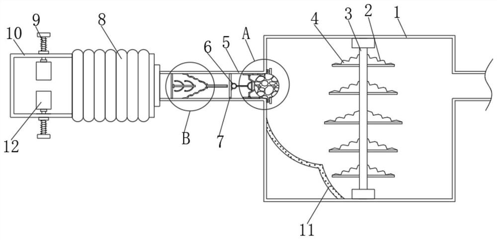
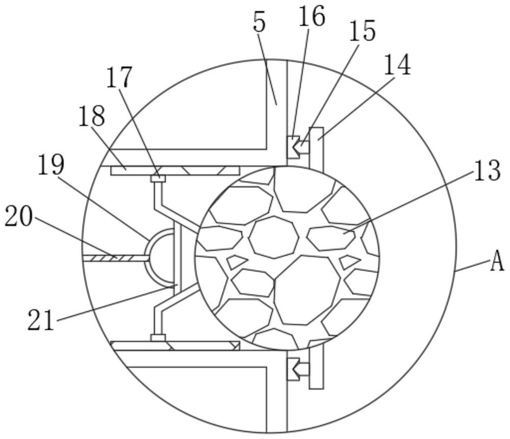
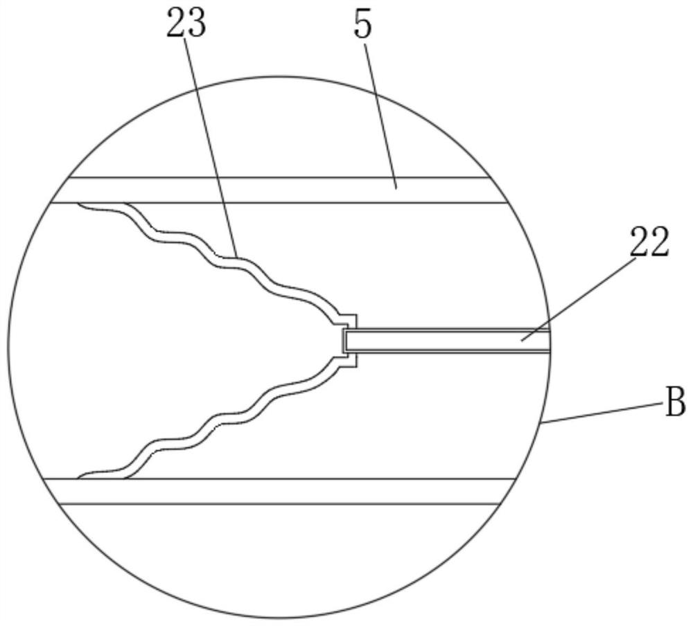
[0028] refer to Figure 1-4 , a chemical distillation kettle and rectification tower connection device, including a surge tank 1, a connecting pipe 5 is plugged into one side of the surge tank 1, and a corrugation is inserted into the end of the connecting pipe 5 away from the surge tank 1 Pipe 8, one end of corrugated pipe 8 is plugged with fixed pipe 10, and the top outer wall of fixed pipe 10 is provided with threaded hole, and the inner thread of threaded hole is connected with fixed screw rod 9, and the outer wall of one end of fixed screw rod 9 is rotatably connected with clamping Ring 12, the top and bottom inner walls of the surge tank 1 are rotatably connected with the first rotating rod 3, and the outer walls on both sides of the first rotating rod 3 are connected with stirring blades 4 by bolts, and one side outer wall of the stirring blade 4 has a Grooves 2 are equidistantly distributed, and the inner walls on both sides of the surge tank 1 are connected with defle...

Embodiment 2

[0032] refer to Figure 5 , a chemical rectification kettle and rectification tower joint device. Compared with embodiment 1, the inner walls of both sides of the connecting pipe 5 are connected with the third connecting rod 26 by bolts in this embodiment, and one part of the third connecting rod 26 The side outer wall is rotatably connected with a second rotating rod 25, and the peripheral outer wall of the second rotating rod 25 is connected with a stirring rod 24 by bolts.

[0033] Working principle: when the water flow flows in the diversion bucket 23, it will drive the second rotating rod 25 and the stirring rod 24 to rotate together, so that the water flow can generate a vortex, making the water flow more rapid, and at the same time, the sealing ball 13 can be easily flushed away .


PUM


Abstract

The invention discloses a device for connecting a chemical rectifying kettle and a rectifying tower. The device comprises a pressure stabilizing box, wherein a connecting pipe is inserted into the outer wall of one side of the pressure stabilizing box, a corrugated pipe is inserted into the end, away from the pressure stabilizing box, of the connecting pipe, a fixing pipe is inserted into one endof the corrugated pipe, a threaded hole is formed in the outer wall of the top of the fixing pipe, a fixing screw rod is in threaded connection with the interior of the threaded hole, a clamping ringis rotatably connected to the outer wall of one end of the fixing screw rod, first rotating rods are rotatably connected to the inner walls of the top and the bottom of the pressure stabilizing box, and stirring blades are arranged on the outer walls of the two sides of each first rotating rod. According to the invention, when materials in the rectifying tower flow into the pressure stabilizing box through the connecting pipe, the sealing ball can be flushed open so as to complete material transfer work, and when the materials flow back in the process of being transferred from the rectifying tower to the rectifying kettle, the elastic rope can recover deformation, so that the sealing ball is pulled to block the connecting pipe so as to effectively avoid the backflow of the materials.

Description

technical field [0001] The invention relates to the technical field of chemical industry, in particular to a device for connecting a chemical distillation kettle and a rectification tower. Background technique [0002] A rectification tower is a tower-type vapor-liquid contact device for rectification. Utilizing the different volatility of each component in the mixture, that is, the property that the vapor pressure of each component is different at the same temperature, the light components (low boilers) in the liquid phase are transferred to the gas phase, while the light components in the gas phase are transferred to the gas phase. The heavy components (high boilers) are transferred to the liquid phase, thus achieving the purpose of separation. Distillation column is also a mass transfer and heat transfer device widely used in petrochemical production. [0003] After retrieval, the Chinese Patent Publication No. is CN208785797U, which discloses a rectification kettle and...

Claims


Application Information

Patent Timeline
Patent Type & Authority Applications(China)
IPC IPC(8): B01D3/14B01D3/32
CPCB01D3/143B01D3/32
Inventor 张行江
Owner 张行江
Learn More