Shielded wire harness

Inactive Publication Date: 2006-05-09
AUTONETWORKS TECH LTD +2
View PDF6 Cites 52 Cited by
  • Summary
  • Abstract
  • Description
  • Claims
  • Application Information

AI Technical Summary

Problems solved by technology

However, in the shielded wire harness of the above described type, since an operation to insert the wire-side terminals into the shield case and an operation to connect the connecting members to the shield case must be repeated the same number of times as the number of terminal poles (that is, the number of shield wires), there is found a problem that it takes much time and labor.
However, since the braided wires constituting

Method used


Image

  • Shielded wire harness
  • Shielded wire harness
  • Shielded wire harness

Examples


Embodiment Construction

[0015]Referring now to the accompanying drawings, a description will be given in detail of a preferred embodiment of the invention.

[0016]Now, description will be given below with reference to FIGS. 1 through 3 of an embodiment embodying the invention.

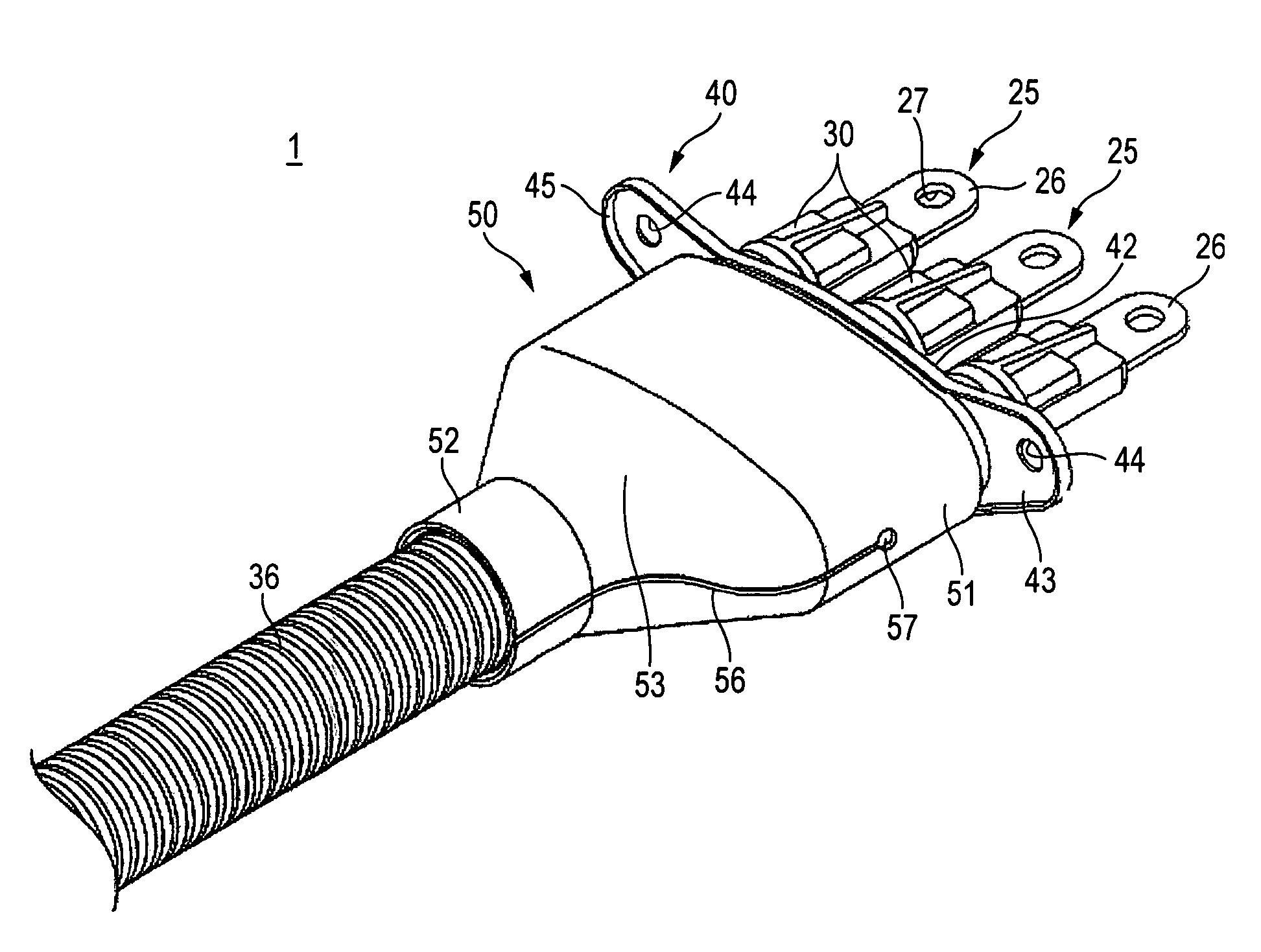
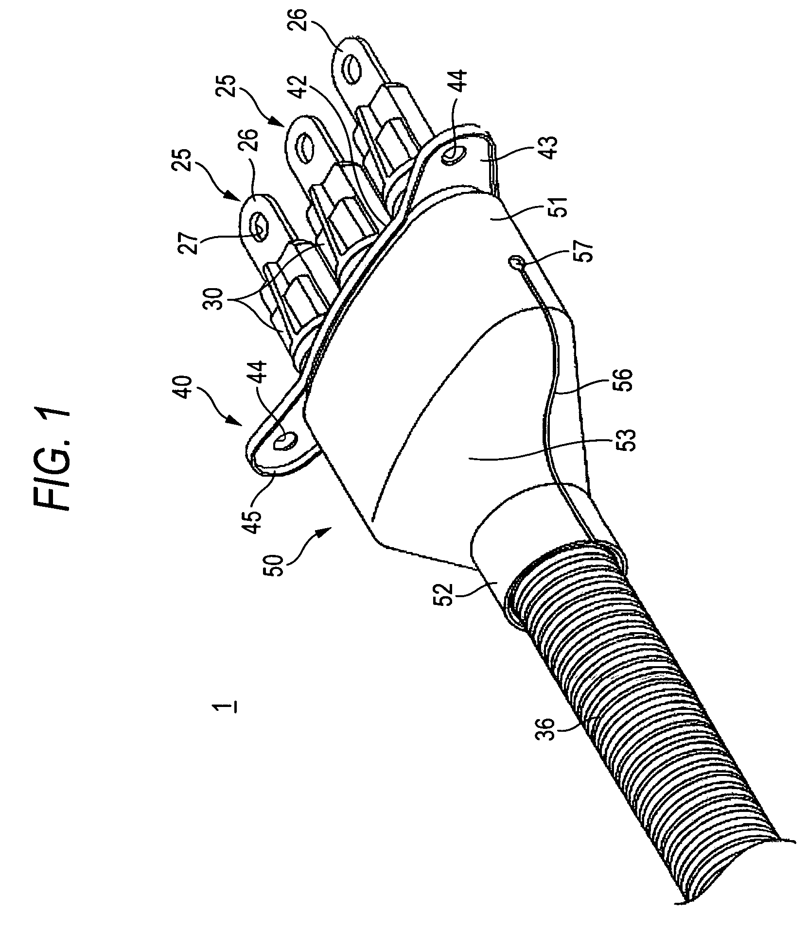
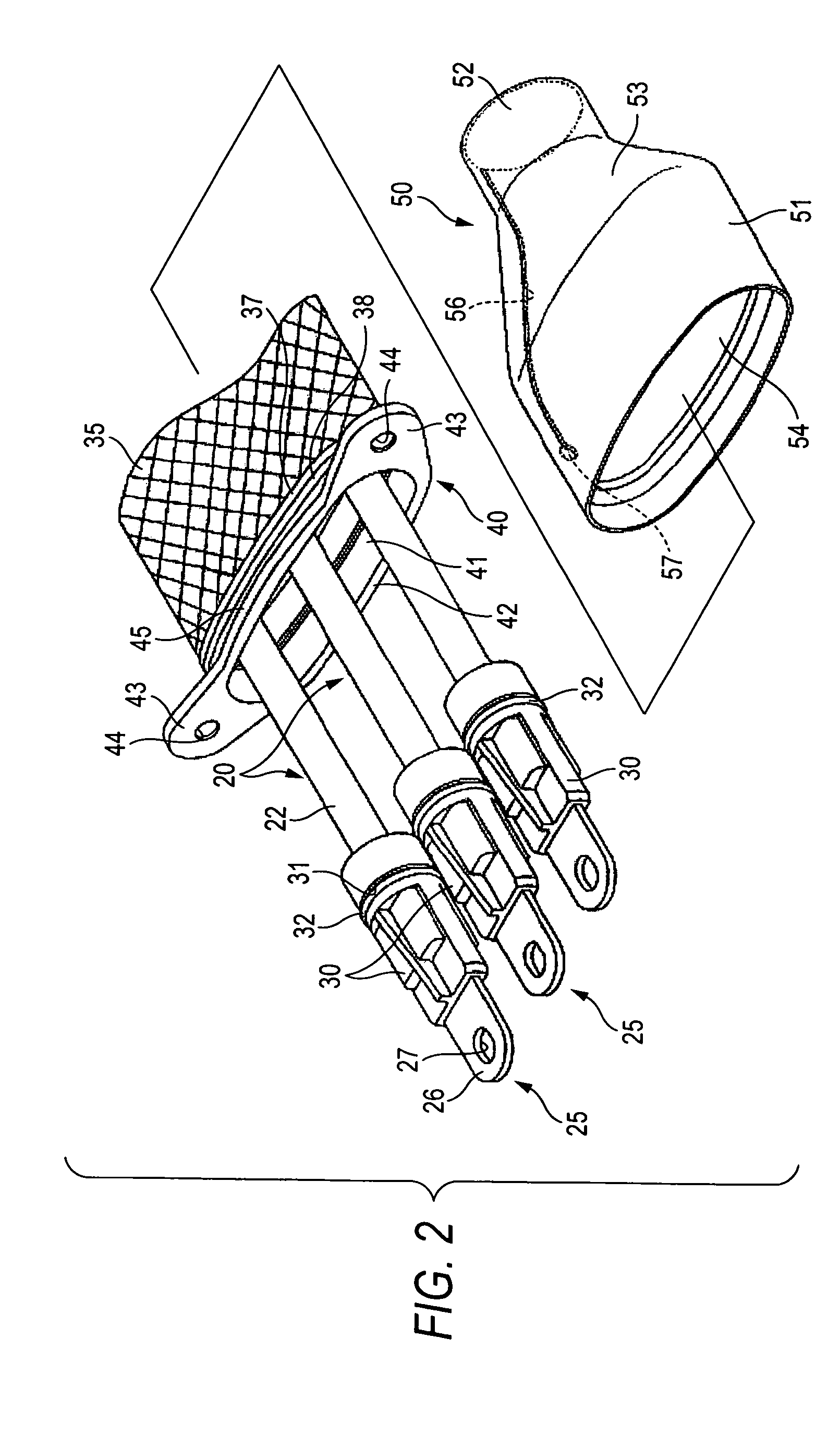
[0017]A shielded wire harness 1 according to the present embodiment is used for connecting together two pieces of equipments such as an inverter unit and a motor in an electric vehicle.

[0018]Equipment 10 is structured such that equipment main body 12 and three equipment-side terminals 13 extended from the equipment main body 12 are stored in a conductive shield case 11. Each of the equipment-side terminals 13 is formed as a plate referred to as a bus bar which is bent substantially in an L-like shape and, in the horizontal portion of the equipment-side terminal, there is formed a bolt hole 14 which penetrates in the vertical direction therethrough. In the side wall of the shield case 11, there are formed three circular-shaped mounting h...


PUM


Abstract

A plurality of wires are enclosed by a shielding member; and the shielding member is enclosed by a protecting member. The shielding member is connected to a shield case of equipment via a shield shell. The shielding member has a diameter-spread portion in which a diameter thereof is spread larger than that of the protecting member at an end portion where the shielding member is projected from the protecting member, and connected to the shield shell at an end edge thereof. The diameter-spread portion is covered by a covering member formed in tube shape.

Description

BACKGROUND OF THE INVENTION[0001]1. Field of the Invention[0002]The present invention relates to a shielded wire harness.[0003]2. Description of the Related Art[0004]For connecting together two pieces of equipment such as an inverter unit and a motor in an electric vehicle, there is used a shielded wire harness. As a shielded wire harness of this type, there is known a shielded wire harness structured such that wire-side terminals are fixed to end portions of conductors of shielded wires, the wire-side terminals connected to equipment-side terminals disposed in a shield case of the equipment, and the shield layers of the shield wires are connected through connecting members to the shield case (see JP-A-11-026093).[0005]However, in the shielded wire harness of the above described type, since an operation to insert the wire-side terminals into the shield case and an operation to connect the connecting members to the shield case must be repeated the same number of times as the number o...

Claims


Application Information

Patent Timeline
IPC IPC(8): H02G1/00H01R4/64H01R11/12H01R13/52H01R13/658H01R13/6581H01R13/6592H05K9/00
CPCH01R13/6592H01R13/6581H01R11/12H01R13/521
Inventor MIYAZAKI, SHO
Owner AUTONETWORKS TECH LTD
Why Eureka
Try Eureka