This helps you quickly interpret patents by identifying the three key elements:
Problems solved by technology
Method used
Benefits of technology
[0004]It is an object of the present invention to provide an electronic key system which prevents a third party from using a stolen or lost key in an attempt of locking / unlocking or vehicle engine starting.
Problems solved by technology
By such a conventional system, however, if the regular key itself is stolen or lost, it may be used to illegally unlock the door or start the engine.
Method used
Image
Click on the blue label to locate the original text in one second.
Reading with bidirectional positioning of images and text.
Examples
first embodiment
[0018]The following will describe in detail a first embodiment implementing the present invention with reference to FIGS. 1 to 4.
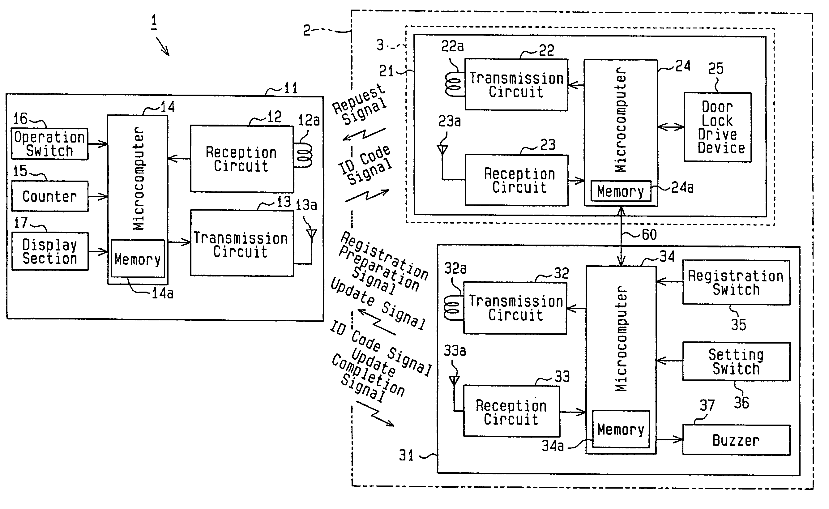
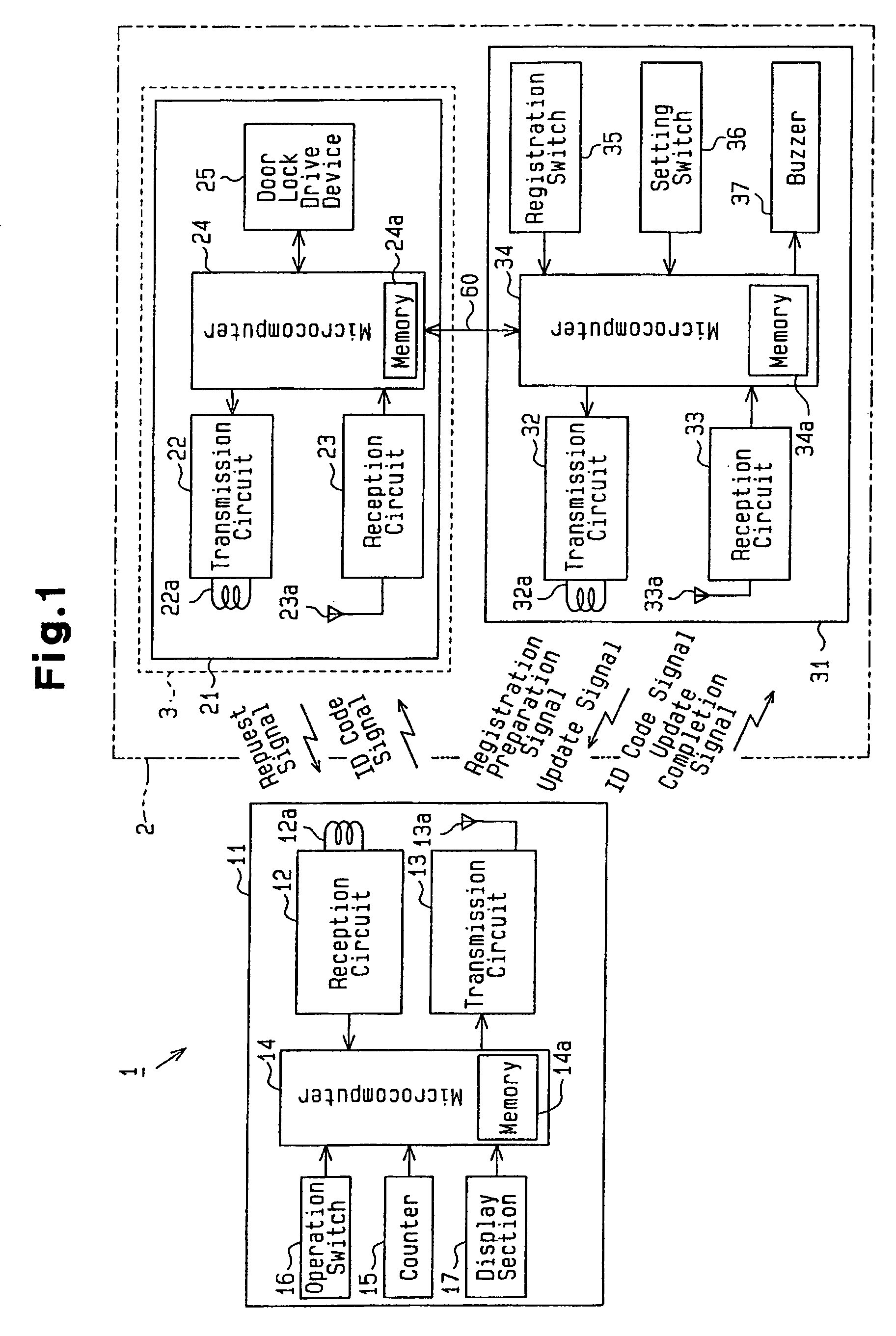
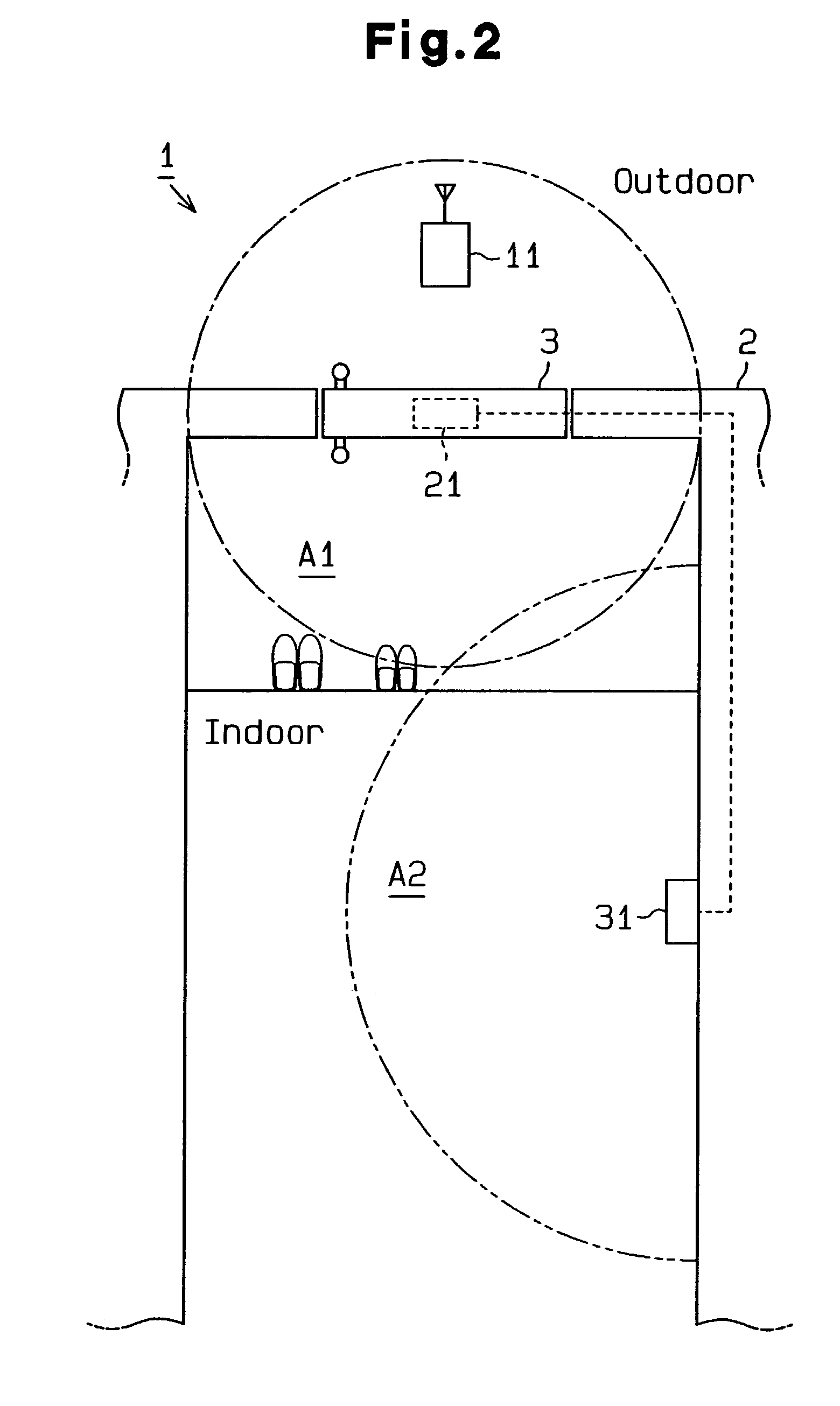
[0019]As shown in FIGS. 1 and 2, an electronic key system 1 comprises a portable apparatus 11 which is carried by the owner (occupant of the house), an operation control device 21, and an update control device 31.
[0020]The portable apparatus 11 is provided with a reception circuit 12, a transmission circuit 13, a microcomputer 14, a counter 15, an operation switch 16, and a display section 17.
[0021]A reception antenna 12a and a microcomputer 14 are connected to the reception circuit 12. The reception circuit 12, when having received through the reception antenna 12a a variety of transmit signals sent from the operation control device 21 or the update control device 31, demodulates these signals into a pulse signal and inputs it to the microcomputer 14.
[0022]A transmission antenna 13a and the microcomputer 14 are connected to the transmission circuit 13. Th...
second embodiment
[0062]The following will describe a second embodiment implementing the present invention with reference to FIGS. 5 to 7. The present embodiment is mainly described on differences from the embodiment of FIGS. 1 to 4, so that components common to these are only indicated by the same reference numerals and their description is omitted.
[0063]As shown in FIG. 5, in a portable apparatus 11 according to the present embodiment, the counter 15 and the display section 17 are omitted from that of the first embodiment. Furthermore, such a use limit value as mentioned above is not recorded in a memory 14a.
[0064]A microcomputer 14 of the portable apparatus 11 receives via a reception antenna 12a a response request signal transmitted from an update control device 31. When having received the response request signal, the microcomputer 14 automatically outputs to a transmission circuit 13 a response signal including an ID code pre-set in the memory 14a.
[0065]An update control device 31 is provided...
PUM
Abstract
An electronic key system has a portable apparatus, an operation control device and an update control device. The portable apparatus selectively transmits a first signal and a second signal. The operation control device authorizes an operation of a key based on reception of the first signal. The update control device transmits an update signal in a private region of the owner of the portable apparatus. The portable apparatus has a counter and a portable apparatus controller. When receiving the update signal, the portable apparatus controller resets the counter. When the counting value of the counter is equal to or less than a predetermined limit value, the controller selects the first signal as a signal to be transmitted. When the counting value is in excess of the limit value, the controller selects the second signal as a signal to be transmitted.
Description
BACKGROUND OF THE INVENTION[0001]The present invention relates to an electronic key system for locking / unlocking a door of, for example, a vehicle or a house or for authorizing (allowing) starting of a vehicle engine.[0002]Conventionally, a key using system such as a vehicle or house door locking device or an engine starter is provided with such an immobilizer function as to authorize locking / unlocking of the door or starting of the engine if an attempted communication is established between the key and the lock. In such a system, it is difficult to duplicate the key and also to unlock the door except by a regular key or start the engine, thus improving security.[0003]By such a conventional system, however, if the regular key itself is stolen or lost, it may be used to illegally unlock the door or start the engine.SUMMARY OF THE INVENTION[0004]It is an object of the present invention to provide an electronic key system which prevents a third party from using a stolen or lost key in ...
Claims
Application Information
Patent Timeline
Application Date:The date an application was filed.
Publication Date:The date a patent or application was officially published.
First Publication Date:The earliest publication date of a patent with the same application number.
Issue Date:Publication date of the patent grant document.
PCT Entry Date:The Entry date of PCT National Phase.
Estimated Expiry Date:The statutory expiry date of a patent right according to the Patent Law, and it is the longest term of protection that the patent right can achieve without the termination of the patent right due to other reasons(Term extension factor has been taken into account ).
Invalid Date:Actual expiry date is based on effective date or publication date of legal transaction data of invalid patent.