Pressure indicator

a technology of pressure indicator and pressure, which is applied in the direction of instruments, mechanical equipment, valve arrangements, etc., can solve the problems of affecting the use of such instruments, affecting the operation of such instruments, etc., and achieves the effect of easy reading of optical indication, convenient mounting and compact construction

Inactive Publication Date: 2006-05-16
GEBRR GLOOR
View PDF10 Cites 9 Cited by
  • Summary
  • Abstract
  • Description
  • Claims
  • Application Information

AI Technical Summary

Benefits of technology

[0004]The object of the invention is to provide a pressure indicator device which allows an easily read-off optical indication of the pressure by the simplest possible mechanical means, is extremely robust in mechanical terms, has a highly compact construction and can easily be mounted on a vessel which is under pressure.
[0012]The pressure indicator device according to the invention can be used in a particularly versatile and simple way when it has the external configuration of a screw with a head part and with a threaded part, and when the optical indicator means are arranged in the head part and the piston is arranged in the threaded part.
[0013]In such a compact pressure indicator device, safety and capability during use under rough conditions can be further increased when a predetermined breaking point is provided between the head part and the threaded part in the housing, when the piston is sealed off below the predetermined breaking point by means of a seal, and when a pressure plate for distributing the piston pressure is arranged between the upper end of the piston and the plunger or the pointer spring.

Problems solved by technology

Pressure surges, mechanical vibrations or even knocks may damage such instruments.
If they are seriously damaged or even broken away, a hole appears which results in the emergence of the fluid or gas.
The construction size does not allow such instruments to be used at all in instances where only a little space is available.

Method used


Image

  • Pressure indicator
  • Pressure indicator
  • Pressure indicator

Examples


Embodiment Construction

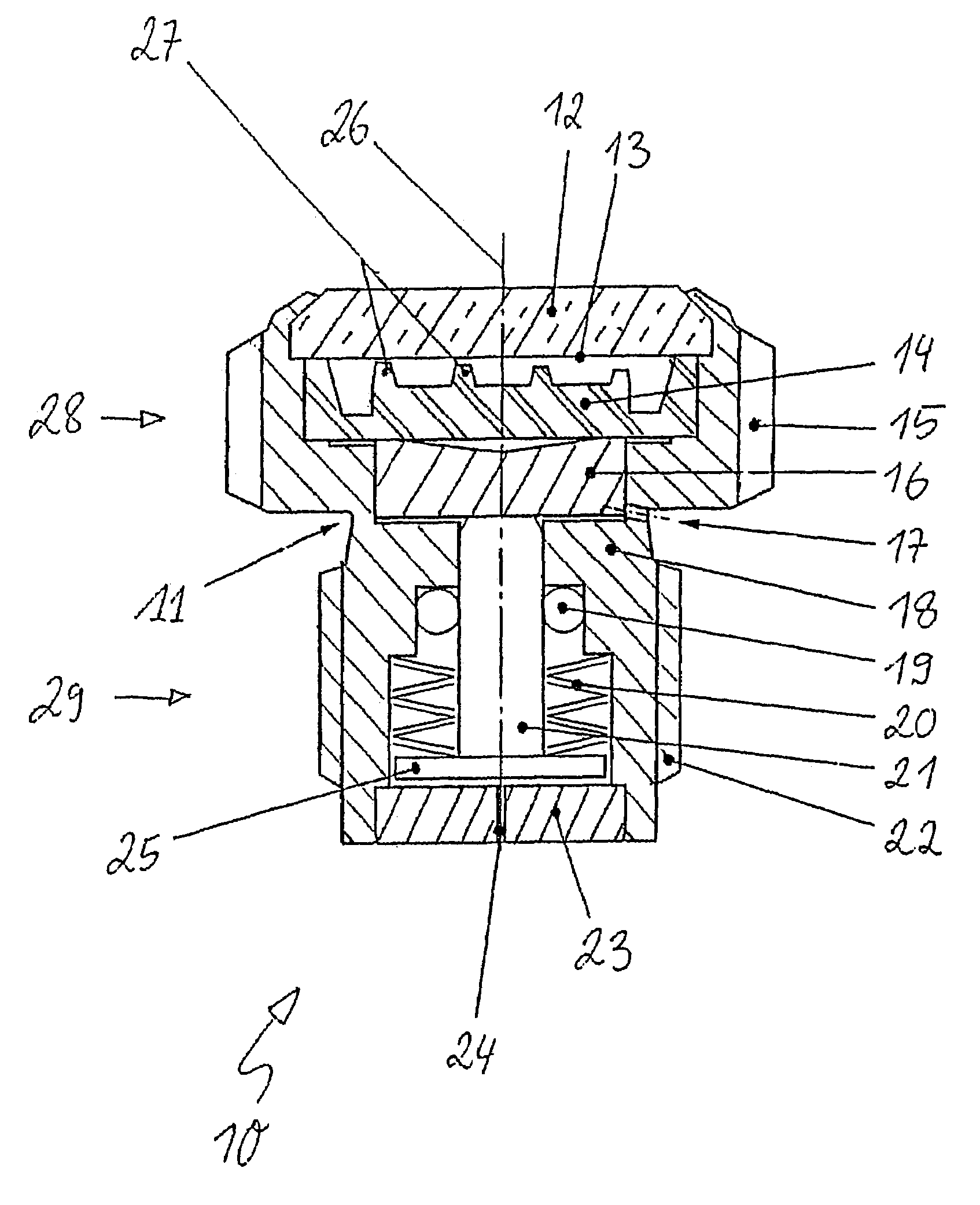
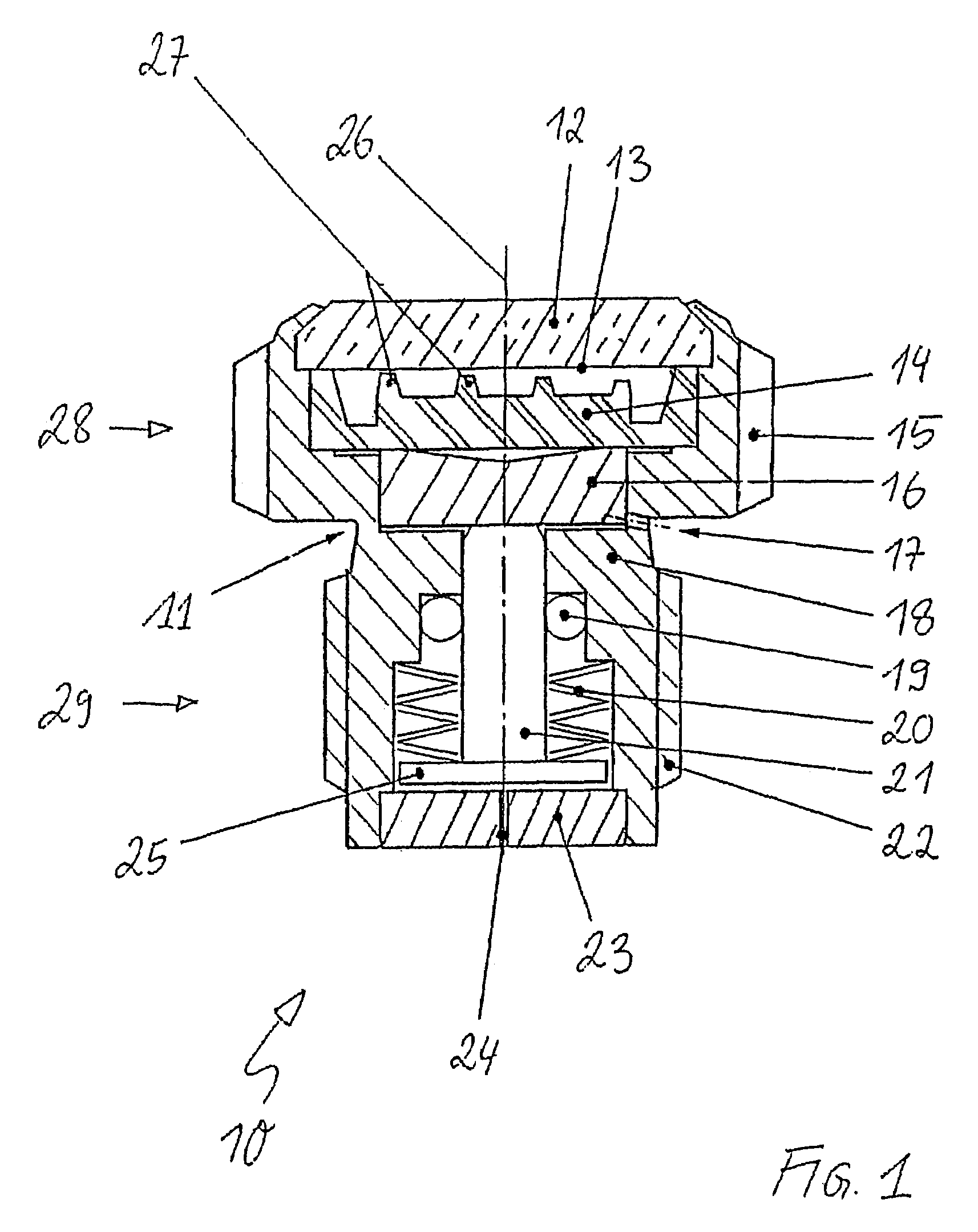
[0019]The first exemplary embodiment, illustrated in FIG. 1, shows a pressure indicator device (pressure indicator) 10 which comprises a one-piece housing (monobloc) 18.

[0020]The housing 18 has the external form of a screw with a screw axis 26 and with a head part (screw head) 28 and a threaded part 29. The housing 18 has in the head part 28 corresponding key faces 15 on the outer circumference. In the low region of the housing 18, the threaded part 29, a screw-in thread 22 is arranged coaxially to the axis 26, by means of which screw-in thread the pressure indicator device 10 can be screwed preferably into a cock attached to a compressed gas bottle. A piston 21 with a head plate 25 is guided in the direction of the axis 26 within the housing portion provided with the screw-in thread 22. The head plate 25 faces the pressure side. A spring 20, which is supported at the lower end on the head plate 25 and at the upper end on the housing 18, acts counter to the piston 21, which is under...


PUM

PropertyMeasurementUnit
diameteraaaaaaaaaa
diameteraaaaaaaaaa
lengthaaaaaaaaaa

Abstract

A pressure indicator comprising a piston which is displaceably mounted in a housing counter to the pressure of a spring on an axis and which can be impinged upon with pressure which is to be measured; also comprising optical display means actively cooperating with the piston. According to the invention, the structure of the indicator is simplified, compact and robust. This is achieved in that the optical display means comprise a front glass arranged perpendicular to the axis and one or several display elements which can be moved by the piston relative to said front glass and which respectively alternate at various pressures between a first position wherein they are optically visible from outside through the front glass and a second position wherein they are not optically visible from outside through the front glass.

Description

FIELD OF THE INVENTION[0001]The present invention relates to the field of the indication of pressures which prevail in a volume filled with a medium, in particular, a gas.DESCRIPTION OF THE RELATED ART[0002]Conventional pressure indicator devices (manometers) indicate the current pressure in a volume filled with a medium, in particular gas, usually on a dial by means of a pointer rotatable about an axis of rotation. The pressure is converted into a small rotational movement by means of a tube spring, capsule spring, plate spring or the like. However, manometers are also known. (JP-A2-04145335), in which, by means of the pressure, a piston arranged in a cylinder is displaced counter to the force of a spring and the displacement travel is converted into a pointer rotation about the axis of displacement. Other manometers such as are used, for example, for indicating tire pressures on a tire valve, indicate the displacement travel of the piston directly on a scale extending in the direc...

Claims


Application Information

Patent Timeline
Patent Type & Authority Patents(United States)
IPC IPC(8): G01L9/00F16K37/00G01L19/12
CPCG01L19/12F16K37/0058
Inventor BERNHARD, ERNST
Owner GEBRR GLOOR
Why Eureka
Try Eureka