Microtome

a microtome and switch technology, applied in the field of microtomes, can solve the problems of serious deficiencies in the operation comfort, correspondingly detrimental effects on the operation comfort, and the switch in the microtome without a regulating function, so as to avoid inconvenient operation.

Inactive Publication Date: 2006-05-16
HESS CONSULTGMBH
View PDF11 Cites 9 Cited by
  • Summary
  • Abstract
  • Description
  • Claims
  • Application Information

AI Technical Summary

Benefits of technology

[0019]Briefly pressing the second operating element in the zero position causes activation by means of the CPU of a pulse function in which a horizontal advance movement of the specimen holding device is effected by the preselected μm-value which has been respectively selected by way of the section thickness preselection as a trimming feed movement or as a section thickness fine feed movement. The advance movement of the specimen holding device is effected in this mode without a vertical upward and downward movement of the specimen holding device having to be performed.
[0020]Such a microtome according to the invention, of the last-mentioned kind, with a first operating element for controlling the vertical upward and downward movement of the specimen holding device and a second operating element for controlling the horizontal reciprocating movement of the specimen holding device, with associated CPU, affords the advantage that for example out of nine operating keys or elements eight operating keys or elements on the operating desk of a conventional microtome can be replaced, namely

Problems solved by technology

In that known microtome therefore there are both a hand wheel and also an operating desk with a multiplicity of keys and switches, that is to say operating elements, so that the operating comfort suffers from serious deficiencies.
In addition the switches in that microtome do not have a regulating function.
In that case therefore, in addition to the hand wheel, the arrangement still requires three different keys or switches, that is to say groups of operating elements, which has a correspondingly detrimental effect on operating comfort.

Method used


Image

  • Microtome
  • Microtome

Examples


Embodiment Construction

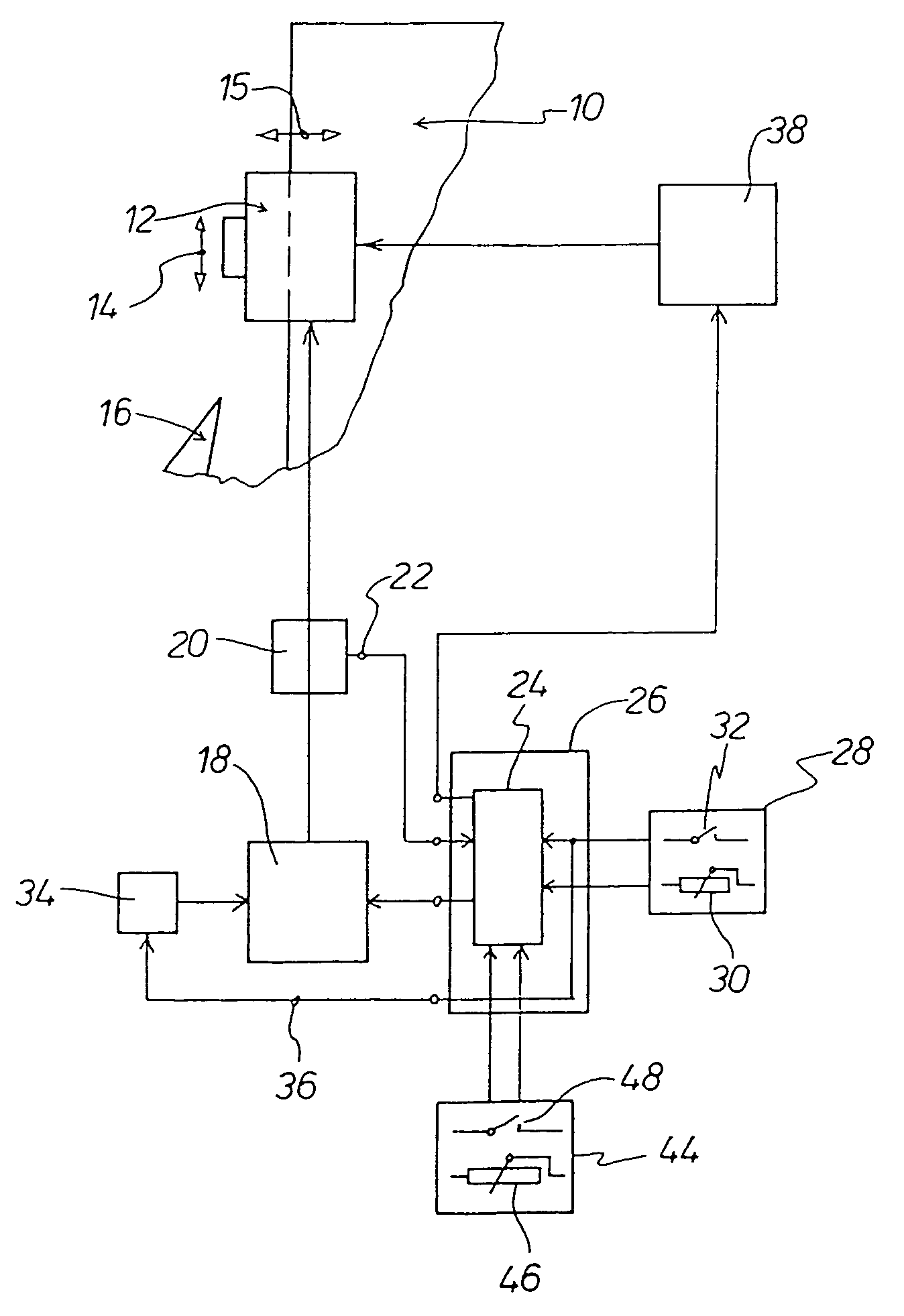
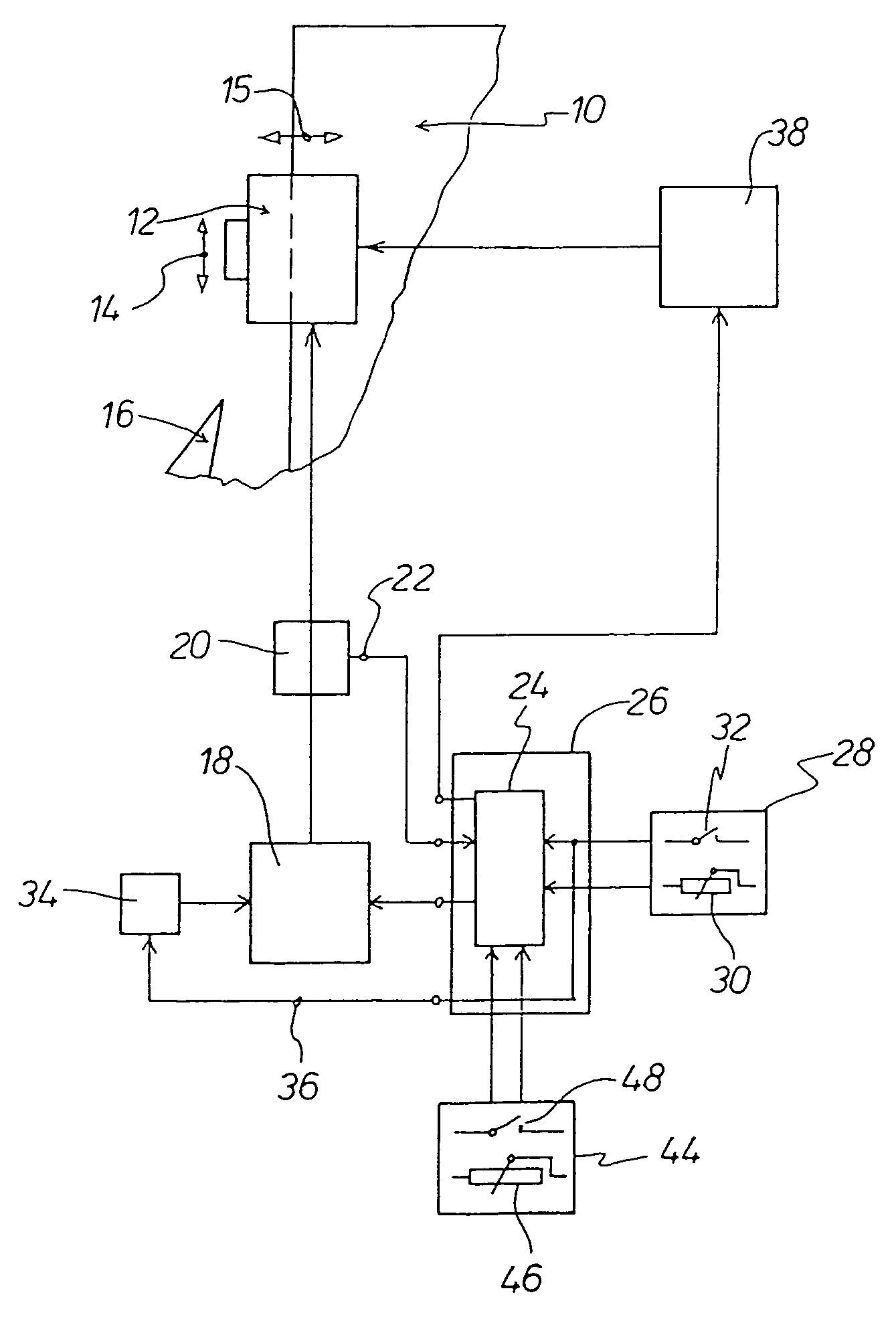
[0032]The FIGURE is a diagrammatic view showing a portion of a base frame 10 of the microtome. A specimen holding device 12 is arranged on the base frame 10 movably vertically upwardly and downwardly and reciprocatingly horizontally. The microtome is a rotational microtome with a specimen holding device 12 which is suitable for performing a vertical upward and downward movement. That movement is indicated by the double-headed arrow 14. The microtome is also suitable for performing a horizontally reciprocating movement indicated by a double-headed arrow 15. Reference numeral 16 denotes a cutting element of the microtome, of which a portion is diagrammatically indicated. The cutting element 16 is a cutting knife or a knife holder with a cutting blade.

[0033]The specimen holding device 12 is connected to an electric motor 18 for implementing the vertical oscillating upward and downward movement indicated by the double-headed arrow 14. The motor 18 is a DC motor. The rotary movement of t...


PUM

PropertyMeasurementUnit
movementsaaaaaaaaaa
relative movementaaaaaaaaaa
speedaaaaaaaaaa

Abstract

A microtome includes a knife holding device for a cutting element (16) and a specimen holding device (12). Associated with the specimen holding device (12) for a cutting movement is a first drive device (18) and associated with the specimen holding device (12) or the knife holding device is a second drive device (38) for a feed movement. A sender (20) is associated with the first drive device (18) and is connected with an electronic control means (26). A first operating element (28) controlling the first drive device (18) has a standard mode, in which the cutting movement of the specimen holding device is controlled by rotation of the first operating element (28), and a second mode, in which a continuous cutting function is activated by pressing the first operating element (28). A second operating element (44) controlling the second drive device (38) also has corresponding rotary and pressing modes.

Description

CROSS REFERENCE TO RELATED APPLICATION[0001]This application is a divisional application of co-pending application Ser. No. 10 / 470,110 which was filed on Apr. 5, 2004.BACKGROUND OF THE INVENTION[0002]The invention concerns a microtome comprising a knife holding device and a specimen holding device, wherein the specimen holding device has a first drive device for performing a cutting movement and the specimen holding device or the knife holding device has a second drive device for performing a feed movement.[0003]Microtomes of that kind are known per se in various different forms. For example the prospectus ‘The MICROM HM 350 S’ from MICROM International, 69190 Waldorf, discloses a microtome in which it is possible to eliminate a hand wheel for manual upward and downward movement of the specimen holding device, that is to say for manually performing a cutting movement. The above-mentioned hand wheel is replaced by an operating element which is for example a rotary knob. By way of an ...

Claims


Application Information

Patent Timeline
Patent Type & Authority Patents(United States)
IPC IPC(8): G01N1/06G01N1/28
CPCG01N1/06G01N2001/2873G01N2001/066Y10T83/141Y10T83/6492Y10T83/061Y10T83/081Y10T83/6499Y10T83/8765
Inventor HESS, HANS-JUERGEN
Owner HESS CONSULTGMBH
Why Eureka
Try Eureka