Two-phase refrigerant distribution system for multiple pass evaporator coils

a technology of evaporator coil and refrigerant distribution system, which is applied in the field of heat exchangers, can solve the problems of significant mal-distribution of liquid refrigerant, and achieve the effect of improving the redistribution of refrigerant flow

Active Publication Date: 2006-05-16
HILL PHOENIX
View PDF5 Cites 42 Cited by
  • Summary
  • Abstract
  • Description
  • Claims
  • Application Information

AI Technical Summary

Benefits of technology

[0004]In accordance with another aspect of the invention, an inductor nozzle is placed in the collection header at the beginning of the second pass. A source of two-phase refrigerant is interconnected to drive the inductor nozzle and to thereby assist in the flow within the bypass tube and along the collection header in the vicinity of the second pass tubes, thereby assisting in the improved redistribution of refrigerant flow into the second pass tubes.

Problems solved by technology

Partly, because of the dissipation of heat and pressure in the first pass, significant mal-distribution of liquid refrigerant tends to occur in the second and subsequent passes.

Method used


Image

  • Two-phase refrigerant distribution system for multiple pass evaporator coils
  • Two-phase refrigerant distribution system for multiple pass evaporator coils

Examples


Embodiment Construction

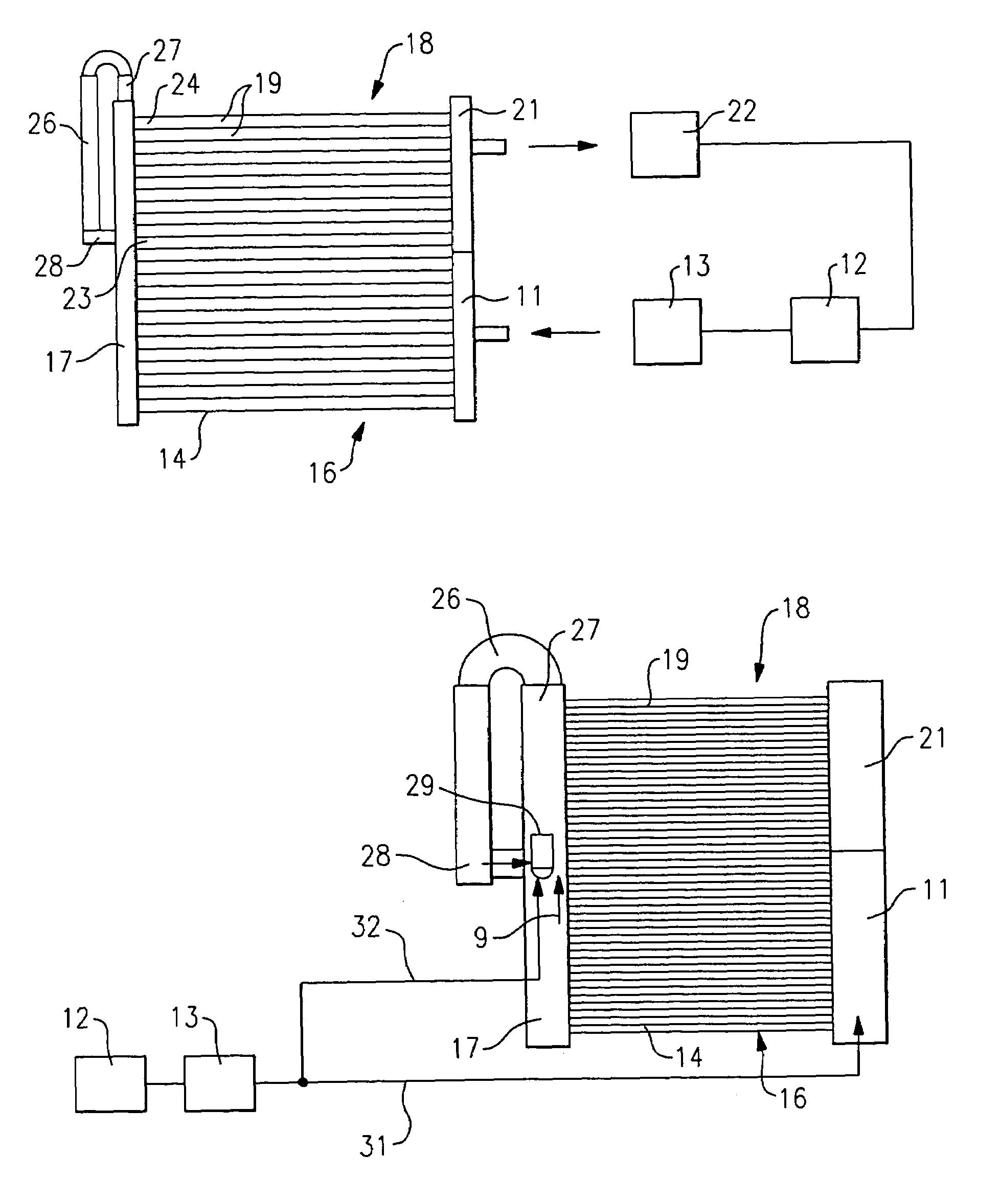
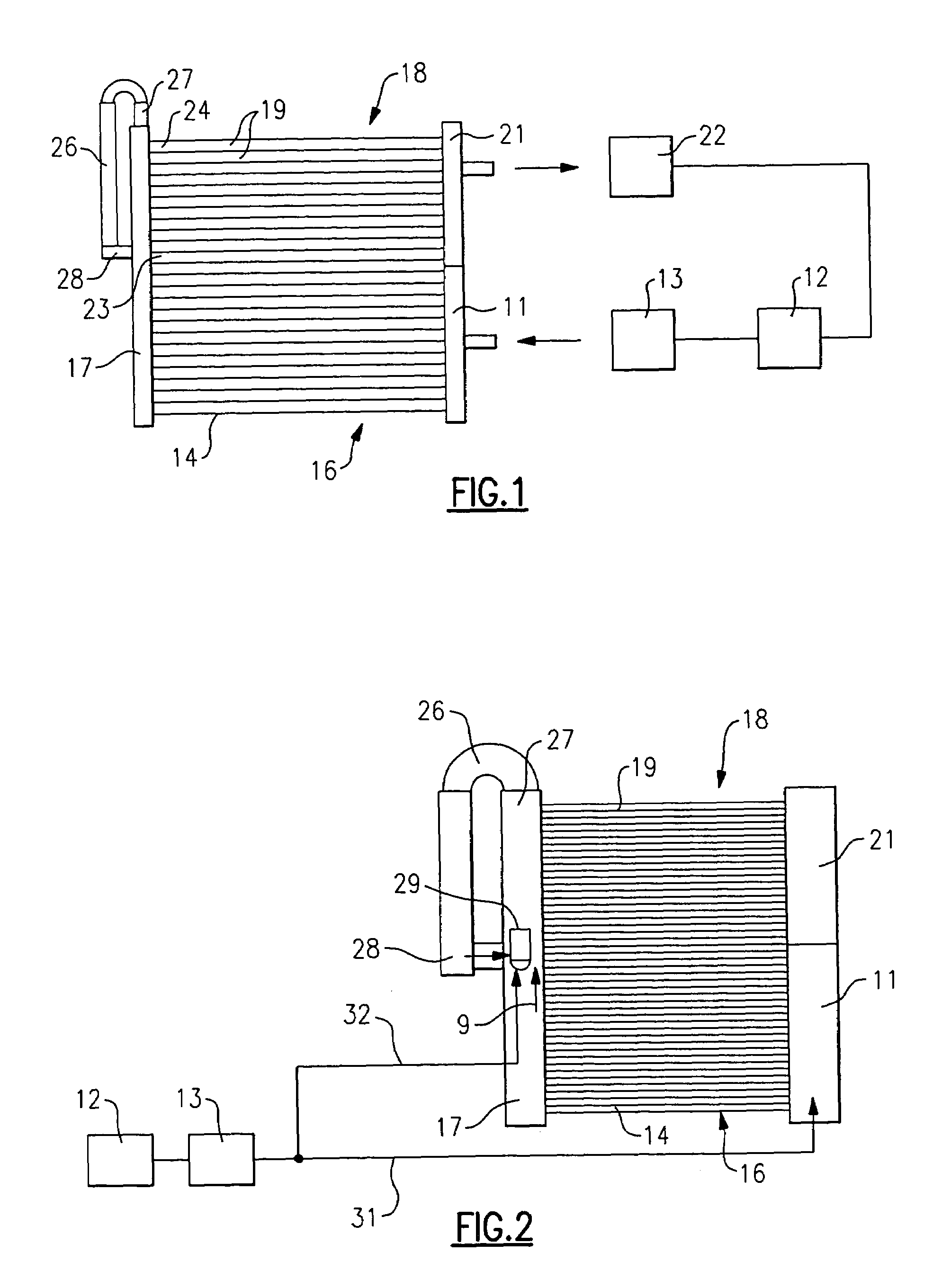
[0008]Referring now to FIG. 1, a heat exchanger is shown to include a first header 11 which receives a flow of two-phase refrigerant from a condenser 12 by way of an expansion device 13 in a conventional manner.

[0009]Fluidly connected to and extending orthogonally from the first header 11 as a plurality of parallel tubes 14 that carry the refrigerant flow in a first pass 16 of the heat exchanger. Fluidly connected at the other end of the tubes 14 is a second header 17 commonly referred to as the collection header. The collection header 17 extends not only along the full length of the first pass tubes but also along the full length of a second pass 18 comprising the parallel tubes 19 for conducting the flow of refrigerant from the second header to a third header 21 which then passes the refrigerant vapor to a compressor 22. From the compressor, the high-pressure vapor is then passed to the condenser 12 to complete the circuit.

[0010]Referring again to the heat exchanger second pass 18...


PUM


Abstract

A multiple pass, parallel tube heat exchanger with a collection header extending along the length of each of a first and second pass, is provided with a bypass tube which fluidly interconnects the downstream end of the collection header to a midpoint thereof, near the end of the first pass tubes and the beginning of the second pass tubes so as to enhance the flow distribution of two-phase refrigerant from the collection header to the second pass tubes. The distribution flow is further enhanced by the insertion of an eductor nozzle within the collection header, and with the inlet of the eductor nozzle being supplied by refrigerant flow from the condenser to thereby provide a motive flow of two-phase refrigerant in the loop which includes the latter half of the collection header and the bypass tubes.

Description

BACKGROUND OF THE INVENTION[0001]This invention relates generally to heat exchangers and, more particularly, to two-phase refrigerant distribution for multipass parallel tube coils. Two-phase flow of refrigerant needs to be uniformly redistributed between passes into several parallel tubes. The refrigerant from the first pass generally exits into a collection header after which it then passes along the header to the entrance area of the second pass. Partly, because of the dissipation of heat and pressure in the first pass, significant mal-distribution of liquid refrigerant tends to occur in the second and subsequent passes.[0002]The above described phenomenon is particularly true in the case of parallel flow heat exchangers that use flat tubes with microchannels, which are widely used in automotive air conditioning as condensers. The tubes are laid in a horizontal direction and are attached to common headers. When operating as a condenser, the heat exchanger performs satisfactorily,...

Claims


Application Information

Patent Timeline
Patent Type & Authority Patents(United States)
IPC IPC(8): F28F27/02F25B39/02F28D1/053
CPCF25B39/02F28F27/02F28D1/05375F25B2341/0011F28F2250/06F28F27/00
Inventor GUPTE, NEELKANTH SHRIDHARSPENCER, STEVEN J.
Owner HILL PHOENIX
Why Eureka
Try Eureka