Cartridge for stapler and stapler
a stapler and stapler technology, applied in the field of staplers, can solve the problems of poor design of staples, difficulty in correct binding, and disc-like pattern parts of staples on the shoulder parts of staples, and achieve the effect of enlarge the shape of the pattern part and firmly bind the sheet materials
- Summary
- Abstract
- Description
- Claims
- Application Information
AI Technical Summary
Benefits of technology
Problems solved by technology
Method used
Image
Examples
second embodiment
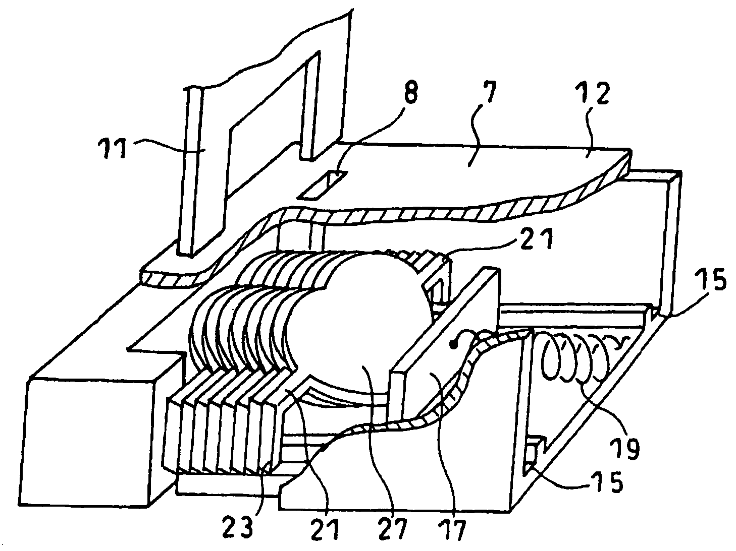
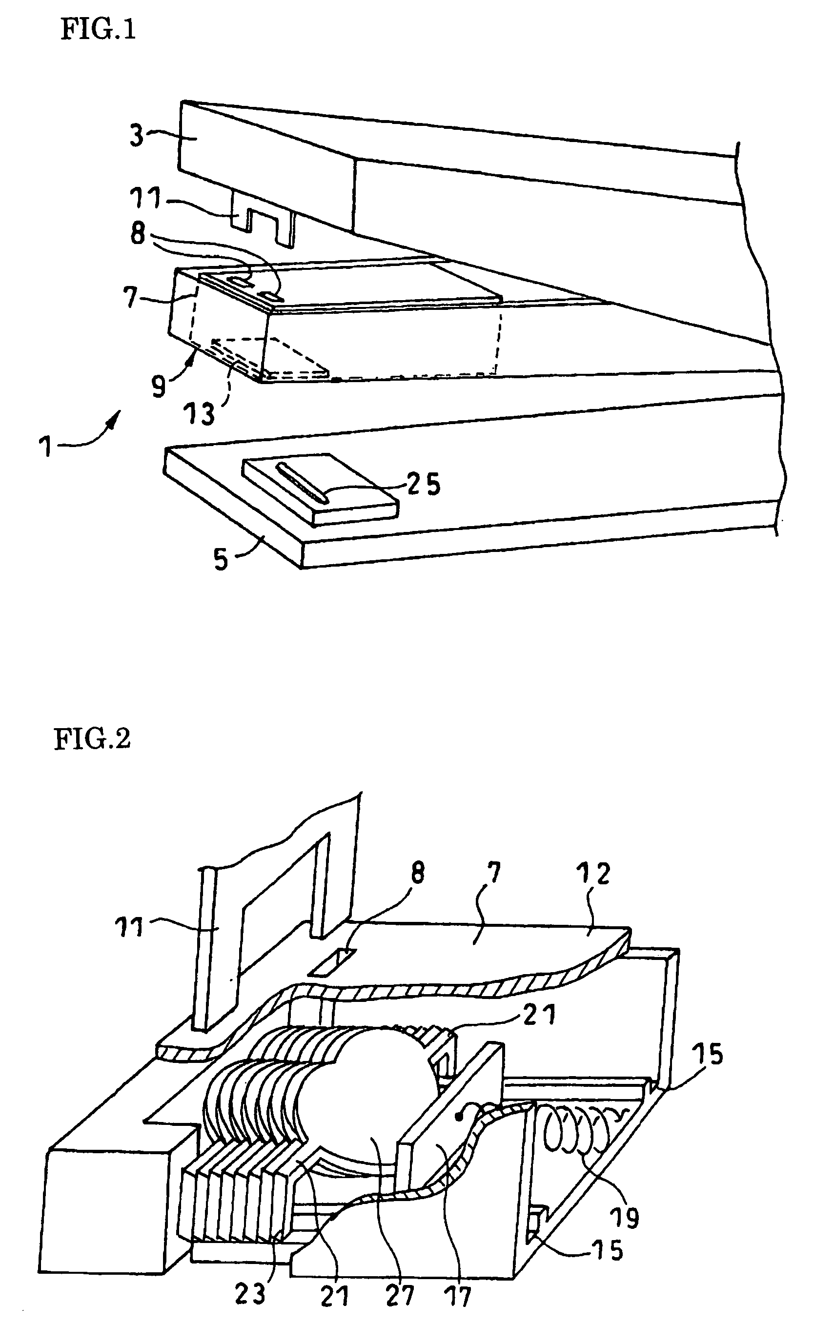
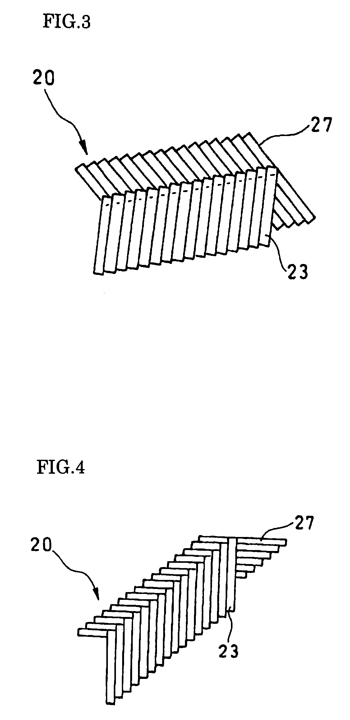
[0036]FIG. 1 is a perspective view schematically illustrating a stapler according to an embodiment of the present invention; FIG. 2 is a perspective view illustrating a structure of a cartridge of FIG. 1; FIG. 3 is a side view of staples stored in the cartridge of FIG. 2; FIG. 4 is a side view illustrating a modification of the staples of FIG. 3; FIG. 5 is a perspective view illustrating a stapler according to the present invention; FIG. 6 is a side view illustrating staples to be stored in the cartridge of FIG. 5; and FIG. 7 is a front view of each staple in a state that sheets of paper are bound.
first embodiment
[0037]A stapler 1 includes a staple receiving base 5 and a retaining part 3 having a staple pusher 11 rotatably provided at an end portion side of the receiving base 5, and a staple storing section 9 is provided between the receiving base 5 and the retaining part 3. A cartridge 7, which has multiple staples 20 for the stapler 1 stored in parallel, is attached to the storing section 9.
[0038]The retaining part 3 includes the staple pusher 11 that pushes out each staple 20 stored in the cartridge 7 through a take-out opening 13, and a central portion of the staple pusher 11 is notched so that the staple pusher 11 abuts against shoulder parts 21 of the staple according to the present invention.
[0039]The receiving base 5 has a groove-like bending section 25 that is placed at a position opposite to the staple pusher 11 of the retaining part 3 and bends leg parts 23 of the staple 21.
[0040]The cartridge 7 has the take-out opening 13 for staple 20 on one side of a case 12. Moreover, a guide...
fifth embodiment
[0059]A modification of the fifth embodiment is next explained. As illustrated in FIG. 12(a), in this modification, a twist is formed in the shoulder parts 21 of the staple 20. The twist is formed by axially rotating the shoulder parts 21 in a direction illustrated by an arrow A, so that the pattern part 27 is easily rotated in the direction illustrated by the same arrow A. In this way, since the twist is formed in the shoulder parts 21, the pattern part 27 can be easily changed from the inclination state against the surface of the sheet material 60 to the parallel state, so that an extra force is not required at the time of binding the sheet materials 60 and a smooth binding operation can be obtained. In addition, it is desirable that the length of the twisting portion should be as short as possible. Since a portion of the shoulder parts 21 in which no twist is formed is flat on its upper surface, the staple pusher 11 easily comes in contact therewith and the staple 20 is smoothly ...
PUM
 Abstract
Description
Claims
Application Information
 - R&D
- Intellectual Property
- Life Sciences
- Materials
- Tech Scout
- Unparalleled Data Quality
- Higher Quality Content
- 60% Fewer Hallucinations
Browse by: Latest US Patents, China's latest patents, Technical Efficacy Thesaurus, Application Domain, Technology Topic, Popular Technical Reports.
© 2025 PatSnap. All rights reserved.Legal|Privacy policy|Modern Slavery Act Transparency Statement|Sitemap|About US| Contact US: help@patsnap.com


