Near-optimal low-complexity decoding of space-time codes for wireless applications
Inactive Publication Date: 2006-05-16
AT&T MOBILITY II LLC
View PDF98 Cites 7 Cited by
Summary
Abstract
Description
Claims
Application Information
AI Technical Summary
This helps you quickly interpret patents by identifying the three key elements:
Problems solved by technology
Method used
Benefits of technology
[0008]Such an approach is achieved with a receiver arrangement where signals received at a plurality of antennas are each multiplied by a respective constant and then summed prior to being applied to a maximum likelihood detector. The respective constants, λj where j is an index designating a particular receiver antenna, are der
Problems solved by technology
Physical constraints as well as narrow bandwidth, co-channel interference, adjacent channel interference, propagation loss and multi-path fading limit the capacity of cellular systems.
These are severe impairments, which liken the wireless
Method used
Image
Click on the blue label to locate the original text in one second.
Reading with bidirectional positioning of images and text.
Examples
Embodiment Construction
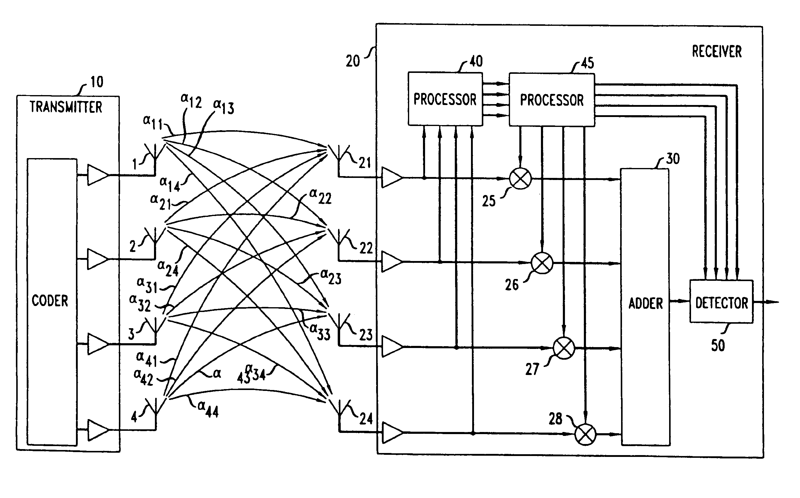
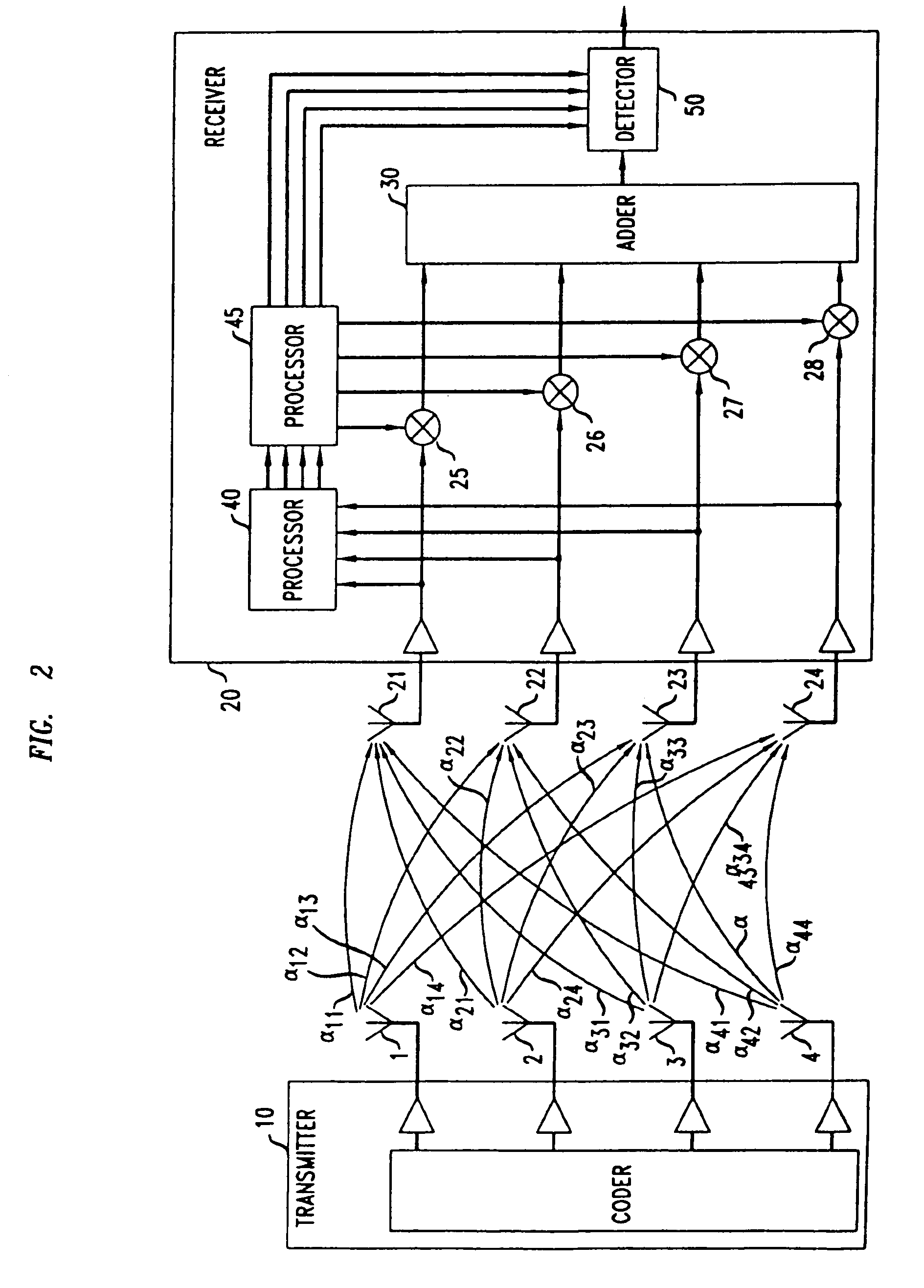
[0011]FIG. 2 presents a block diagram of a receiver in accord with an embodiment of the invention. It includes a transmitter 10 that has an n plurality of transmitting antenna 1, 2, 3, 4, and a receiver 20 that has an m plurality of receiver antennas 21, 22, 23, 24. The signals received by the receiver's antennas are multiplied in elements 25, 26, 27, and 28, and summed in adder 30. More specifically, the received signal of antenna j is multiplied by a value, λj, and summed. The collection of factors λj can be viewed as a vector Λ. The outputs of the receiver antennas are also applied to processor 40 which, employing conventional techniques, determines the transfer functions αij for i=1, 2, 3, . . . , n and j=1, 2, 3, . . . , m. These transfer functions can be evaluated, for example, through the use of training sequences that are sent by the different transmitter antennas, one antenna at a time.
[0012]The evaluated αij signals of processor 40 are applied to processor 45 in FIG. 2 whe...
PUM
Abstract
An improved multi-antenna receiver is realized for detecting signals transmitted by a multi-antenna transmitter by summing signals received at the plurality of receiver antennas after multiplying each by a respective constant. The summed signal is applied to a maximum likelihood detector. The respective constants, λj, where j is an index designating a particular receiver antenna, are determined by evaluating the largest eigenvector of the matrix A, where Λ is a vector containing the values λj, and A is a matrix containing elements αij, which is the transfer function between the ith transmitter antenna to the jth receiver antenna. The αij terms are determined in the receiver in conventional ways.
Description
REFERENCE TO RELATED APPLICATIONS[0001]This application is a continuation of U.S. patent application Ser. No. 10 / 234,407, filed Sep. 3, 2002, now U.S. Pat. No. 6,741,635 which is a continuation of U.S. patent application Ser. No. 09 / 690,542, filed Oct. 17, 2000 (now U.S. Pat. No. 6,470,043), which is a continuation of U.S. patent application Ser. No. 09 / 063,765, filed Apr. 21, 1998 (now U.S. Pat. No. 6,188,736), which claims the benefit of U.S. Provisional Application No. 60 / 068,613, filed Dec. 23, 1997.BACKGROUND OF THE INVENTION[0002]This invention relates to wireless systems and, more particularly, to systems having more than one antenna at the receiver and at the transmitter.[0003]Physical constraints as well as narrow bandwidth, co-channel interference, adjacent channel interference, propagation loss and multi-path fading limit the capacity of cellular systems. These are severe impairments, which liken the wireless channel to a narrow pipe that impedes the flow of data. Neverth...
Claims
Application Information
Patent Timeline
Application Date:The date an application was filed.
Publication Date:The date a patent or application was officially published.
First Publication Date:The earliest publication date of a patent with the same application number.
Issue Date:Publication date of the patent grant document.
PCT Entry Date:The Entry date of PCT National Phase.
Estimated Expiry Date:The statutory expiry date of a patent right according to the Patent Law, and it is the longest term of protection that the patent right can achieve without the termination of the patent right due to other reasons(Term extension factor has been taken into account ).
Invalid Date:Actual expiry date is based on effective date or publication date of legal transaction data of invalid patent.