Display apparatus

a display device and display screen technology, applied in the field of display devices, can solve the problems of degrading picture quality, difficult to secure a sufficient sampling time for sequential sampling of all pixels, and the line potential does not completely return, so as to prevent a vertical streak and increase the ghost margin

Inactive Publication Date: 2006-05-23
SONY CORP
View PDF11 Cites 6 Cited by
  • Summary
  • Abstract
  • Description
  • Claims
  • Application Information

AI Technical Summary

Benefits of technology

[0023]The present invention has been made in view of the above problems, and it is accordingly an object of the present invention to provide a display apparatus that can realize perfect non-overlap sampling in horizontal driving by the clock driving method, and which can thereby prevent a vertical streak caused by overlap sampling and increases the ghost margin.

Problems solved by technology

As a result, the variation in the sampled potential appears as a vertical streak on the display screen, thus degrading picture quality.
When the number of pixels in a horizontal direction, in particular, is increased with higher definition in the active matrix liquid crystal display apparatus of the dot-sequential driving type, it is difficult to secure a sufficient sampling time for the sequential sampling for all the pixels of the video signal “video” inputted by one system within a limited horizontal effective period.
However, because of a large amount of overlap, the signal line potential does not completely return to the gray level.
Therefore, the ghost margin is correspondingly limited.

Method used


Image

  • Display apparatus
  • Display apparatus
  • Display apparatus

Examples


Embodiment Construction

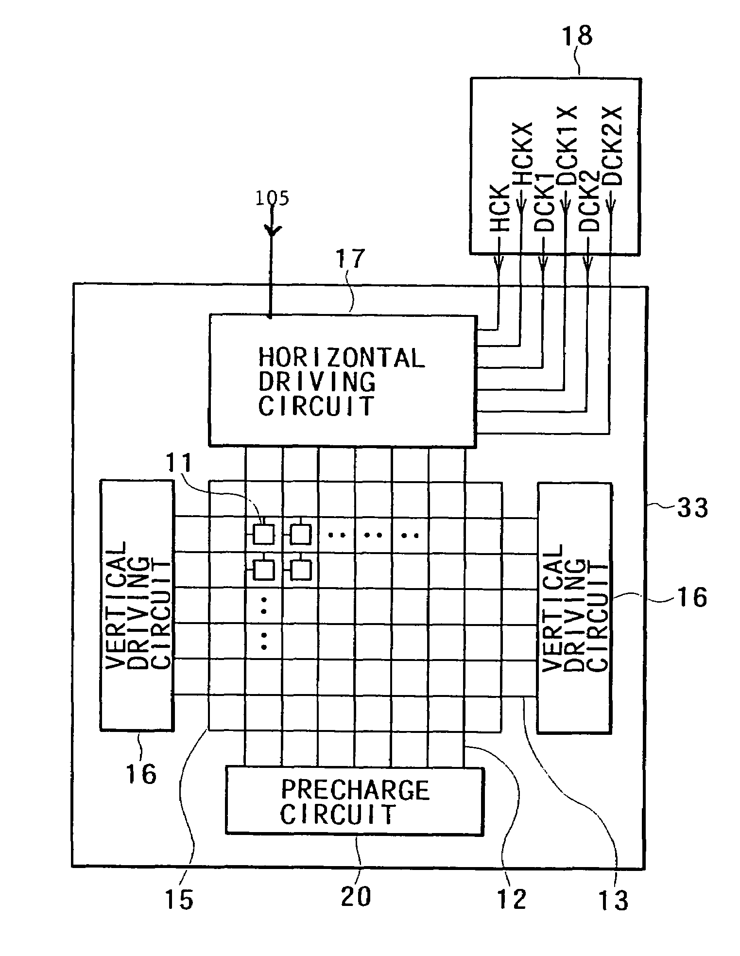
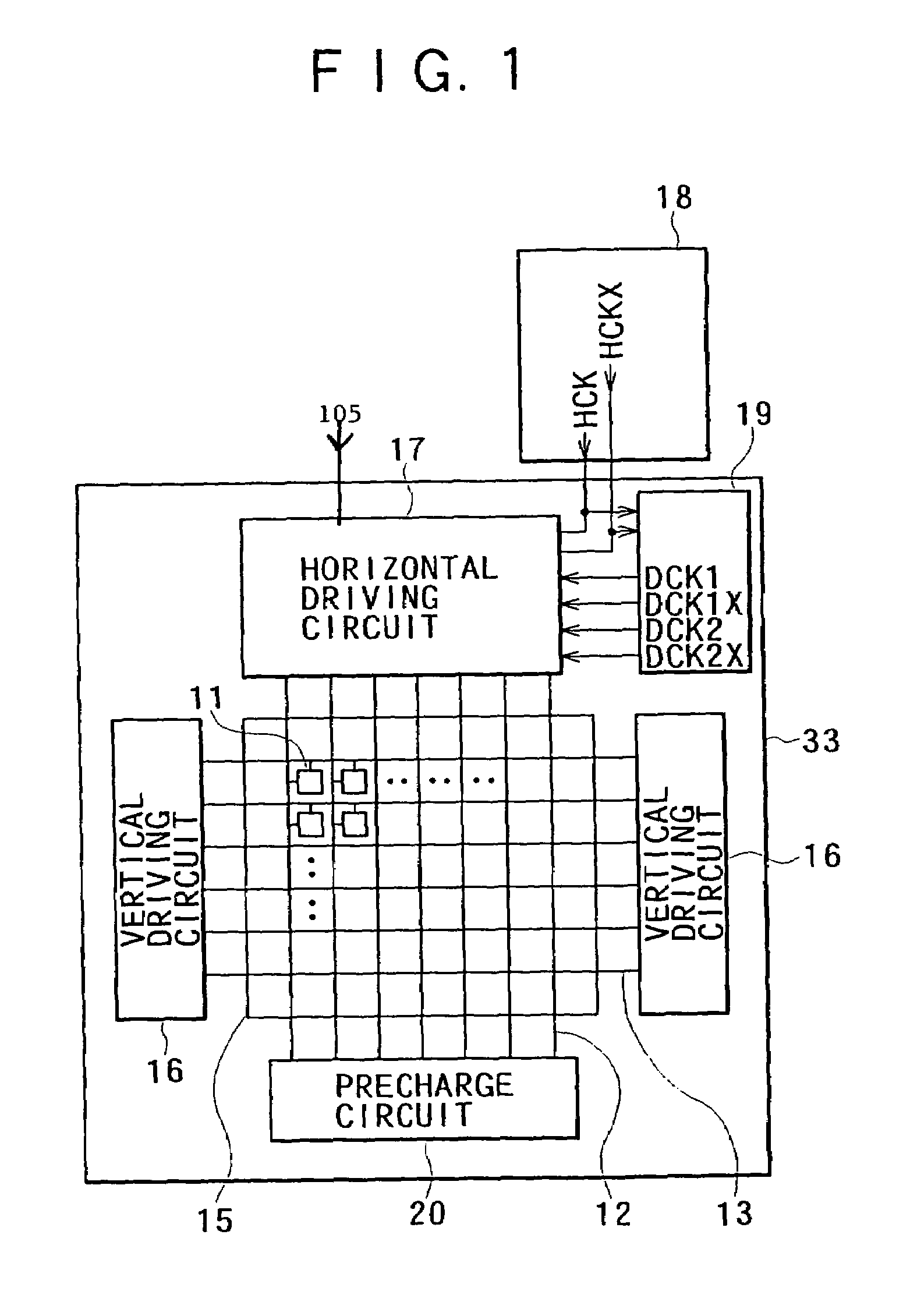
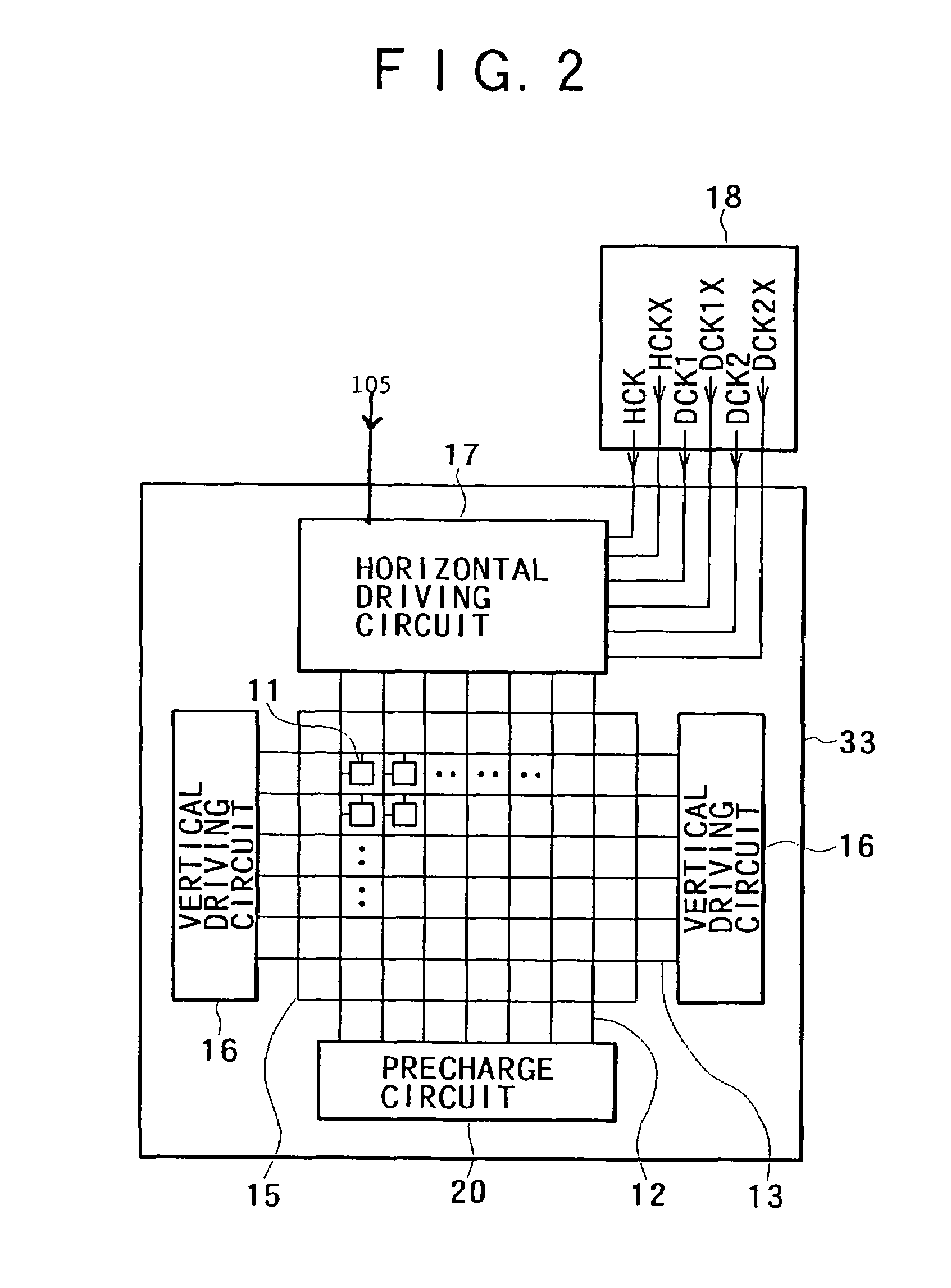
[0055]A preferred embodiment of the present invention will hereinafter be described in detail with reference to the drawings. FIG. 1 is a schematic block diagram showing a basic configuration of a display apparatus according to the present invention. As shown in FIG. 1, the display apparatus is formed by a panel 33 having a pixel array unit 15, a vertical driving circuit 16, a horizontal driving circuit 17 and the like formed therein in an integrated manner. The pixel array unit 15 is formed by gate lines 13 in the form of rows, signal lines 12 in the form of columns, and pixels 11 arranged in a matrix manner at intersections of the gate lines 13 and the signal lines 12. The vertical driving circuit 16 is divided into circuits disposed on the left and right sides, which circuits are connected to both ends of the gate lines 13 to sequentially select a row of the pixels 11. The horizontal driving circuit 17 is connected to the signal lines 12. The horizontal driving circuit 17 operate...


PUM

PropertyMeasurementUnit
widthaaaaaaaaaa
phaseaaaaaaaaaa
wiring resistanceaaaaaaaaaa

Abstract

A horizontal driving circuit includes: a shift register for performing shift operation in synchronism with a first clock signal HCK and sequentially outputting a shift pulse from each of shift stages thereof; a first switch group for extracting a second clock signal DCK in response to the shift pulse sequentially outputted from the shift register; and a second switch group for sequentially sampling an input video signal in response to the second clock signal DCK extracted by each switch of the first switch group, and supplying the sampled video signal to each of signal lines. An external clock generating circuit is disposed external to a panel to externally supply the horizontal driving circuit with the first clock signal HCK, and an internal clock generating circuit is disposed within the panel to internally supply the horizontal driving circuit with the second clock signal DCK.

Description

[0001]This application claims priority to Japanese Patent Application Number JP2001-254800 filed Aug. 24, 2001, which is incorporated herein by reference.BACKGROUND OF THE INVENTION[0002]The present invention relates to a display apparatus, and particularly to an active matrix display apparatus of a dot-sequential driving type using a so-called clock driving method in a horizontal driving circuit thereof.[0003]In a display apparatus, for example an active matrix liquid crystal display apparatus using a liquid crystal cell as a display element (electro-optical element) of a pixel, a horizontal driving circuit of a dot-sequential driving type using a clock driving method, for example, is known. FIG. 13 shows a conventional example of the clock driving type horizontal driving circuit. In FIG. 13, the horizontal driving circuit 100 has a shift register 101, a clock extracting switch group 102, and a sampling switch group 103.[0004]The shift register 101 is formed by “n” shift stages (tr...

Claims


Application Information

Patent Timeline
Patent Type & Authority Patents(United States)
IPC IPC(8): G09G3/36G02F1/133G09G3/20G09G5/18
CPCG09G3/3688G09G3/3648G09G3/20G09G5/18G09G3/36
Inventor UCHINO, KATSUHIDEYAMASHITA, JUNICHI
Owner SONY CORP
Why Eureka
Try Eureka