Layered rotational graphics driver

a graphics driver and rotating display technology, applied in the direction of instruments, geometric image transformation, computing, etc., can solve the problems of compromising compatibility with most applications, requiring extensive effort and validation, and developing a full display driver which supports rotating displays

Inactive Publication Date: 2006-05-23
INTEL CORP
View PDF3 Cites 13 Cited by
  • Summary
  • Abstract
  • Description
  • Claims
  • Application Information

AI Technical Summary

Problems solved by technology

Conventional rotation systems have the disadvantage that an existing display driver must be replaced by a new driver to support a rotated display.
Development of a full display driver which supports a rotated display requires extensive effort and validation, since the driver would need to perform graphical operations in rotated form.
This approach results in the disadvantage that the pixels of

Method used


Image

  • Layered rotational graphics driver
  • Layered rotational graphics driver
  • Layered rotational graphics driver

Examples


Embodiment Construction

[0014]In the following detailed description of embodiments of the invention, reference is made to the accompanying drawings in which like references indicate similar elements, and in which, by way of illustration, specific embodiments in which the invention may be practiced are shown. These embodiments are described in sufficient detail to enable those skilled in the art to practice the invention, and it is to be understood that other embodiments may be utilized and that logical, mechanical, electrical, functional and other changes may be made without departing from the scope of the present invention. The following detailed description is, therefore, not to be taken in a limiting sense, and the scope of the present invention is defined only by the appended claims.

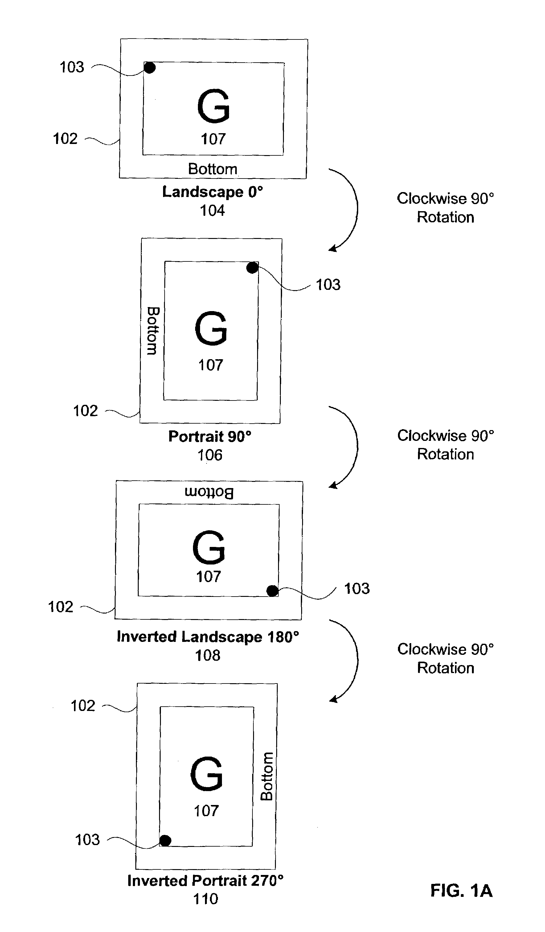
[0015]FIG. 1A illustrates an embodiment of rotation of a display device 102. In one embodiment, display device 102 is a graphical display device which displays pixels organized into scan lines, which are displayed sequentia...


PUM


Abstract

A method and apparatus for a layered rotational graphics driver are described. A rotation driver is loaded. The rotation driver is layered between a graphics device interface and a display driver. The rotation driver allocates a first memory space and the display driver allocates a second memory space. An image is rendered into the first memory space. The image has a first orientation within the first memory space. The image is rotated from the first memory space into the second memory space. The image has a second orientation within the second memory space. The image is displayed in the second orientation from the second memory space.

Description

TECHNICAL FIELD[0001]This disclosure relates generally to computer displays and specifically to rotation of computer displays.BACKGROUND INFORMATION[0002]Computer displays typically are constructed in a manner to display text and other video information in a landscape mode. There have been some displays that are constructed to display video data in portrait mode. To bridge the gap between the two modes of displays, some have built software drivers to enable a display to be rotated between landscape and portrait mode (e.g. typically 90° or 270°) and then to trigger a software switch (either automatically or under user-controlled input) in order to render the image “right-side up.”[0003]One approach has been to provide a display driver which uses a back buffer and a front buffer. The back buffer is a memory surface which has an orientation which is natural for the hardware, while the front buffer is in the natural orientation of the display device. The back buffer is an opaque surface...

Claims


Application Information

Patent Timeline
IPC IPC(8): G09G5/38G06T3/60G09G5/00G09G5/39
CPCG06T3/606G09G5/39G09G2340/0492
Inventor WYATT, DAVIDSRINIVASAN, MALAYALA R.
Owner INTEL CORP
Why Eureka
Try Eureka