Connector capable of being firmly fixed to an object and a fixing member used in the connector

a technology of fixing member and connector, which is applied in the direction of electrical equipment, substation/switching arrangement details, coupling device connections, etc., can solve the problems of difficult to obtain sufficient bearing force against an external force, the lock pin may be undetectedly released,

Active Publication Date: 2006-05-30
JAPAN AVIATION ELECTRONICS IND LTD
View PDF13 Cites 26 Cited by
  • Summary
  • Abstract
  • Description
  • Claims
  • Application Information

AI Technical Summary

Benefits of technology

[0005]It is therefore an object of this invention to provide a connector which can be firmly fixed to an object so that a soldering portion of a contact is hardly subjected to a stress during a mounting operation and during use.

Problems solved by technology

With the above-mentioned structure, if the connector is carelessly attached to a printed board or if the connector is improperly attached, the lock pin may be undesiredly released.
With the above-mentioned structure, a sufficient bearing force against an external force is difficult to obtain because the press-fit portion and the fixing leg of the metal fixture are separated from each other.

Method used


Image

  • Connector capable of being firmly fixed to an object and a fixing member used in the connector
  • Connector capable of being firmly fixed to an object and a fixing member used in the connector
  • Connector capable of being firmly fixed to an object and a fixing member used in the connector

Examples


Embodiment Construction

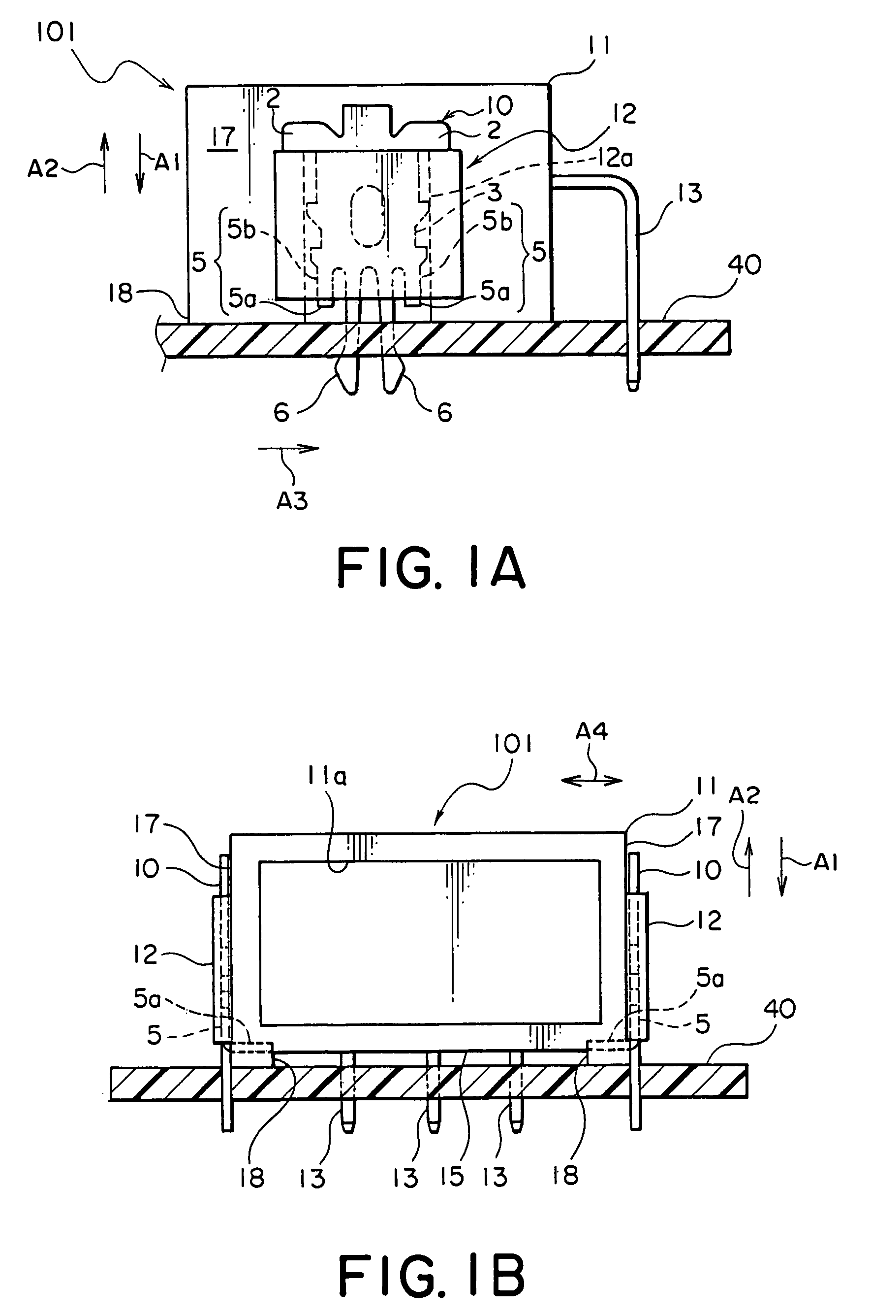
[0019]Referring to FIGS. 1A and 1B, description will be made of a connector according to a first embodiment of this invention.

[0020]In FIGS. 1A and 1B, the connector is depicted at 101. The connector 101 is mounted on a board 40 in a first direction A1 and is fixed to the board 40 by soldering. The connector 101 can be removed form the board 40 in a second direction A2 opposite to the first direction A2.

[0021]The connector 101 comprises a box-shaped insulator 11 and a pair of receiving portions 12 formed on front and rear surfaces 17 of the insulator 11, respectively. The insulator 11 has a fitting portion 11a formed on one of its side surfaces to receive a mating connector in a third direction A3 perpendicular to the first and the second directions A1 and A2. The mating connector can be removed from the fitting portion 11a in a direction opposite to the third direction A3.

[0022]The receiving portions 12 protrude from the front and the rear surfaces 17 of the insulator 11. The insul...


PUM


Abstract

In a connector including an insulator and a contact held by the insulator, a fixing member is coupled to the insulator for fixing the insulator to an object. The fixing member includes a main body received in a receiving portion formed to the insulator. A leg mechanism extends from the main body for being fixed to the object. In addition, a first engaging mechanism extends from the main body and is engaged with the receiving portion in a first direction. On the other hand, the second engaging mechanism extends from the main body and is engaged with the insulator in a second direction opposite to the first direction.

Description

[0001]This application claims priority to prior Japanese patent application JP 2004-100384, the disclosure of which is incorporated herein by reference.BACKGROUND OF THE INVENTION[0002]This invention relates to a connector to be fixed to a board or substrate and a fixing member for fixing the connector to the board.[0003]For example, Japanese Unexamined Patent Application Publication (JP-A) No. H9-283223 discloses an electrical connector. The electrical connector comprises a contact, an insulator holding the contact, a metal shell covering the insulator, and a lock pin as a fixing member. The lock pin is press-fitted into an engaging groove of the insulator by the use of a jig or tool. In order to press-fit the lock pin, the engaging groove is slightly smaller in size than the lock pin. With the above-mentioned structure, if the connector is carelessly attached to a printed board or if the connector is improperly attached, the lock pin may be undesiredly released.[0004]Japanese Unex...

Claims


Application Information

Patent Timeline
Patent Type & Authority Patents(United States)
IPC IPC(8): H01R13/60H01R13/73H01R12/14H01R12/70
CPCH01R12/7029
Inventor HARA, SEIICHIISHIWA, TADASHIHAYASHI, YASUFUMI
Owner JAPAN AVIATION ELECTRONICS IND LTD
Why Eureka
Try Eureka