
Braking device, and method of manufacture

a technology of braking device and cylinder, which is applied in the direction of fluid coupling, rotary clutch, servomotor, etc., can solve the problems of incorrect reinforcement of the region subject to the pulling out force, and excessive work of the cylinder casing sheet metal, so as to reduce the number of parts needed, increase the production cost of the booster, and reduce the effect of the number of parts

Inactive Publication Date: 2006-09-12
ROBERT BOSCH GMBH
View PDF1 Cites 1 Cited by
  • Summary
  • Abstract
  • Description
  • Claims
  • Application Information

AI Technical Summary

Benefits of technology

This approach reduces manufacturing time and costs by eliminating the need for precise screw placement and reinforcement, while providing better stress distribution and increased resistance to braking forces without the need for thick reinforcements or localized stress points.

Problems solved by technology

The regions subjected to the pulling-out forces are therefore not correctly reinforced.
The sheet metal of the cylinder of the casing will experience excessive work under braking, and will weaken.
This weakening leads to yielding of the sheet metal at the location of the fixing region, and to the master cylinder becoming detached.
This results in a significant loss of time.
This loss of time has an impact on the cost of manufacture of the booster.
Finally, the number of parts needed for attachment (screws, reinforcements, nuts) in part explains the high cost of manufacture of a booster.

Method used


Image

  • Braking device, and method of manufacture
  • Braking device, and method of manufacture
  • Braking device, and method of manufacture

Examples


Embodiment Construction

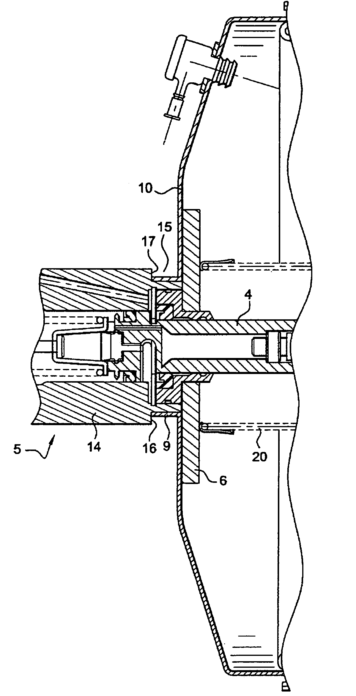
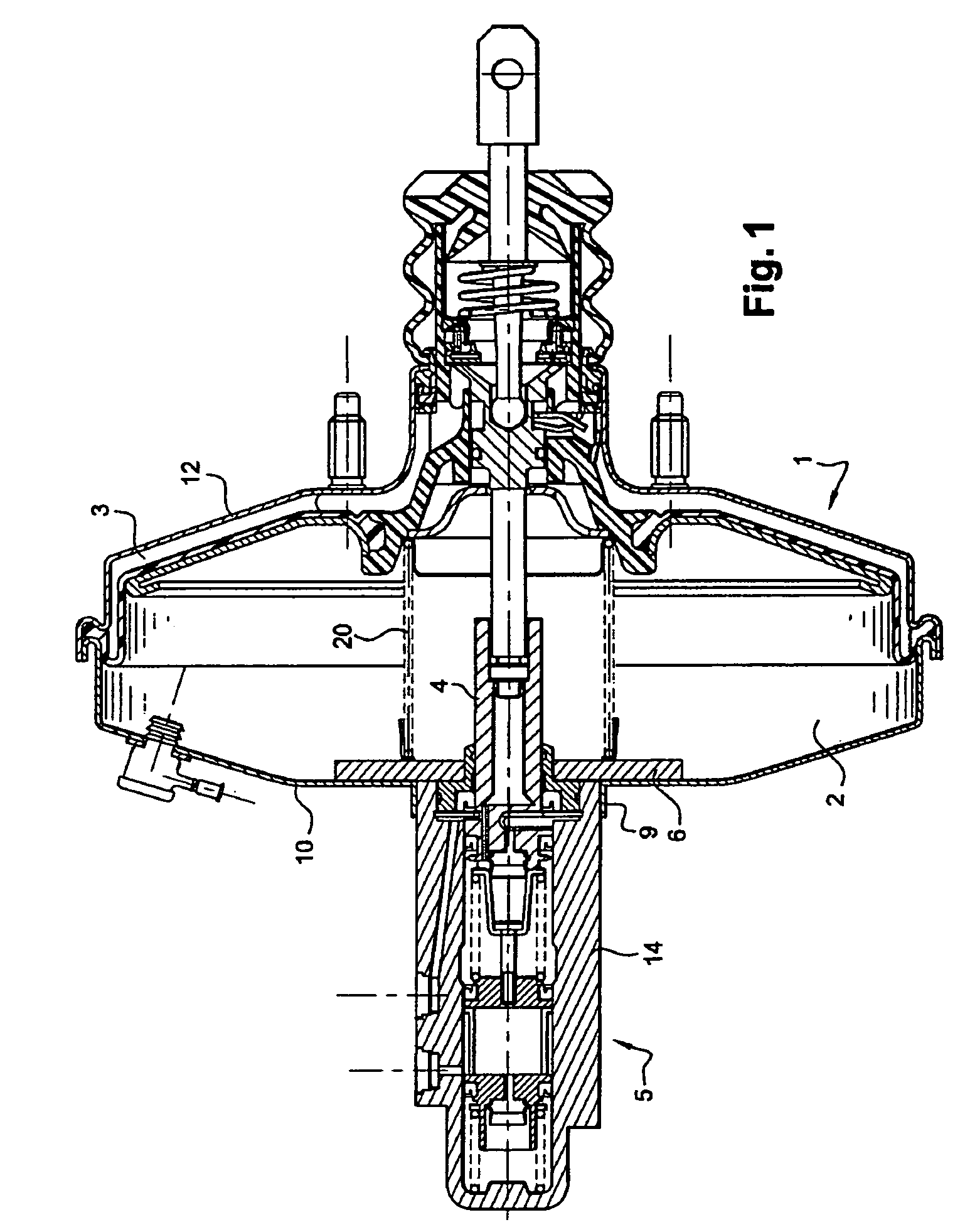
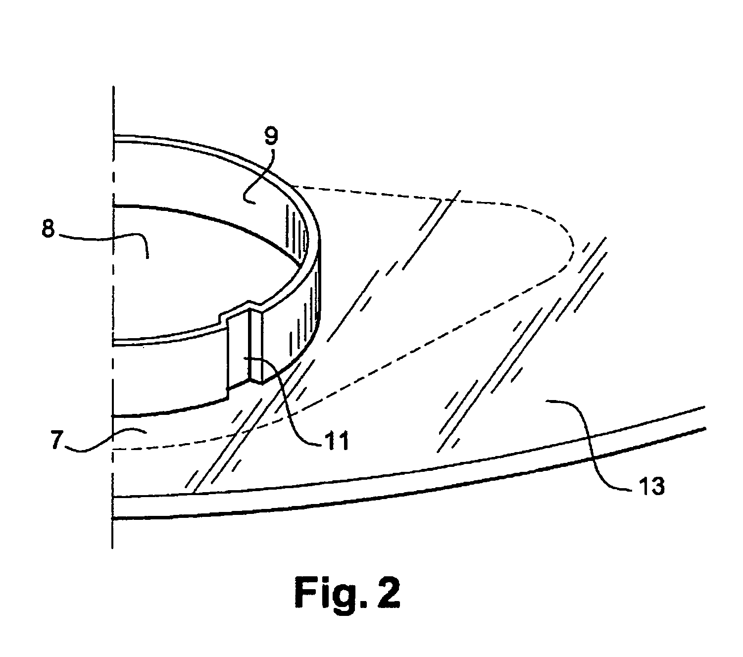
[0031]FIG. 1 gives a good view of how a master cylinder is mounted from inside a booster as prescribed by the invention. A booster 1 is closed at its ends by a cover 12 and a cylinder 10. The cylinder 10 comprises a flat face 7 and an inclined face 13 (FIG. 2). The inclined face 13 extends from the edge of the flat face 7 to a cylinder edge of the cylinder 10. The booster 1 is equipped with a front chamber 2 pneumatically connected to a rear chamber 3. To denote the interior of the booster, the term generally used is a pneumatic envelope. Housed in the front chamber 2 is a penetration snout 4 of a master cylinder 5. A penetration snout is understood to mean part of the body 14 of the master cylinder 5 housed inside the booster 1. The master cylinder 5 is equipped with a master cylinder flange 6. The flange 6 is mounted on a body 14 of the master cylinder 5 at the location of the penetration snout 4.

[0032]Formed on the face 7 of the cylinder 10 is an orifice 8 (FIG. 2) allowing the p...


PUM


Abstract

A braking device and a method of manufacture of such a braking device. The braking device has a booster (1) formed of a cover (12) and of a cylinder (10). A central orifice (8) is formed on the cylinder. A master cylinder (5) has a body (14) that partially enters the booster via the central orifice. The master cylinder is fixed to the cylinder of the booster by plastic deformation of a hollow shaft (9). The hollow shaft borders the central orifice and extends towards the outside of the envelope and penetrates at least one orifice made in an exterior surface of the body of the master cylinder. The cylinder has a flat face that surrounds the central orifice such that a flange (6) extends radially towards the outside of the body of the master cylinder and bears more or less flat against the flat face of the cylinder.

Description

[0001]The present invention relates to a pneumatic brake booster for a motor vehicle. It is aimed at the mounting of a master cylinder on a booster casing and of a method of manufacturing such an assembly. More specifically, it is aimed at a system for fixing the master cylinder to the casing.[0002]The object of the invention is to secure the master cylinder and the casing together effectively. Another object of the invention is to distribute over a large area the stresses which are exerted in the region of attachment of the master cylinder to the casing. An additional object of the invention is to reduce the number of parts needed for manufacturing such an assembly, and the time taken to manufacture a booster, and the cost price of a pneumatic booster. Another object of the invention is to propose a method of manufacturing such a booster.BACKGROUND OF THE INVENTION[0003]A pneumatic brake booster for a motor vehicle generally comprises a casing with a wall made of sheet metal. The c...

Claims


Application Information

Patent Timeline
Patent Type & Authority Patents(United States)
IPC IPC(8): F15B9/10B60T13/00B60T11/16B60T13/56B60T13/565B60T13/567F16B5/04
CPCB60T13/567B60T13/565
Inventor REBOH, JACQUESSAMSON, GWENAEL
Owner ROBERT BOSCH GMBH
Learn More