Container with a hermetic closure

a technology of hermetic closure and container, which is applied in the direction of closures, packaging, and latching mechanisms, can solve the problems of cumbersome lids, less thickness, and less stress on the lid, so as to reduce stress, reduce stress, and reduce the effect of lid stress

Active Publication Date: 2020-02-13
BOTTGER BETTINA
View PDF0 Cites 0 Cited by
  • Summary
  • Abstract
  • Description
  • Claims
  • Application Information

AI Technical Summary

Benefits of technology

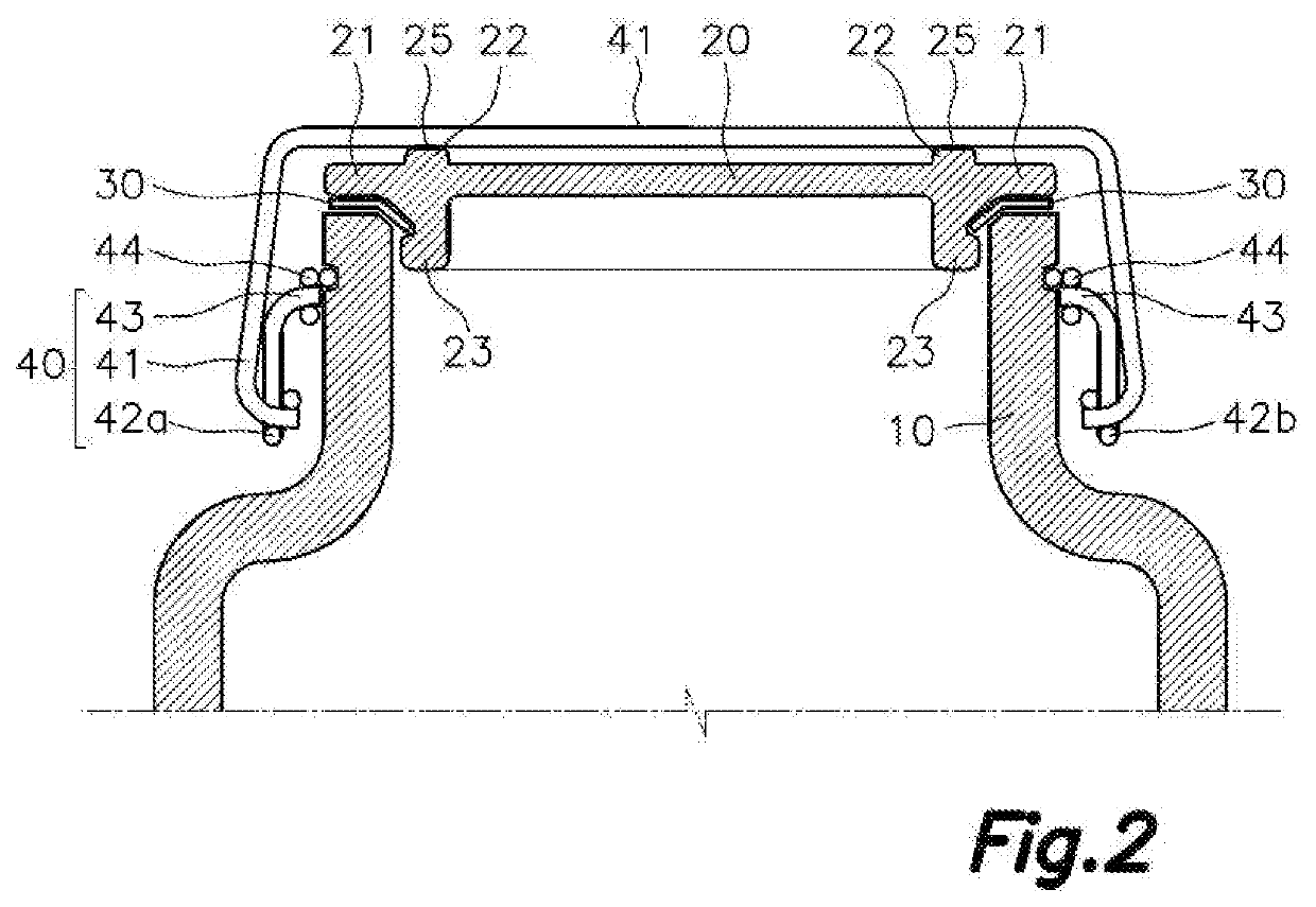
[0034]With the annular closure rib located on the flange, the force exerted on the annular closure rib is transmitted, compressing the annular flange, directly to the mouth of the receptacle, and therefore subjecting the lid to very little stress.
[0035]This feature allows reducing the stresses that must be withstood by the lid, or at least the central areas of said lid, therefore allowing the use of a lid having a little thickness, and therefore being very lightweight and cost-effective.

Problems solved by technology

However, this solution presses the central part of the lid in an area away from the perimeter where sealing takes place, so pressure is not exerted at the point where its effect may be the most beneficial to assure proper sealing, whereby an irregular or poor sealing may take place.
To prevent this defect, it is often decided to apply a large amount pressure in that central part, thereby assuring that sufficient pressure exists on the entire perimeter to assure sealing which, however, requires that central part of the lid to have a significant thickness and a convex shape to enable withstanding that stress and therefore results in a very heavy lid that is therefore cumbersome, expensive to manufacture, and has a significant environmental impact.
Both the length of the metal wire and the distance existing between the lever mechanism and the supporting point are two factors that negatively affect stresses said wire withstands.
With the length of the metal wire and the distance between supporting points thereof being increased by the use of a convex lid with a central support, it is required to use a stronger metal wire that is therefore more expensive to manufacture with respect to other solutions which allow reducing the total length of the wire and placing the supporting points of the wire on the lid closer to the lever mechanisms at the sides of the receptacle.
This solution allows providing a flat lid, but pressure is applied in an asymmetrical manner only on one side of the lid, so the sealing is irregular and a large amount of pressure must be applied to assure proper sealing, a very thick and heavy lid being needed to withstand and distribute that pressure, said lid therefore being expensive to manufacture, cumbersome, and having a significant environmental impact.
Other solutions are also known in which the wire is attached in an articulated manner on two opposite sides of the edge of the lid, as described in document EP3205596A1, for example, however this solution also requires a lid with a very thick edge to enable including that articulated attachment, which likewise results in a very heavy lid that is expensive to manufacture and has a high environmental impact.
Solutions in which the metal wire of the closure mechanism goes through the lid through a hole are also known, however this solution again requires a lid with a significant thickness, and therefore, a significant weight.
However, this solution does not allow a simultaneous closing and opening of the container as a whole, and the quality of the sealing will depend on the number and position in which said clamps or fasteners are placed.
Furthermore, it cannot be assured that all the clamps or fasteners exert the same pressure on the lid, due to the fact that each fastener may have been used a different number of times or subjected to different stresses when being placed or removed, and therefore undergone different fatigue or deformation processes, or due in addition to the fact that the different clamps or fasteners correspond to different manufacturing batches.
Therefore, the attainment of a uniform hermetic closure on the entire perimeter of the lid cannot be assured, which means that an overpressure must be exerted to assure that all the points of the perimeter of the lid are sufficiently closed.
Furthermore, this solution easily leads to the loss of said clamps or fasteners or to one or more of the clamps or fasteners being released due to an accidental, inconsequential blow, with the hermetic sealing of the container being accidentally released.
None of the known solutions provides a hermetic closure which assures pressure in the entire contact area between the lid and the mouth of the receptacle, assuring a sufficient hermetic sealing, and which can be opened or closed with a single action and at the same time allows using a lightweight lid.

Method used


Image

  • Container with a hermetic closure
  • Container with a hermetic closure
  • Container with a hermetic closure

Examples


Embodiment Construction

[0065]The attached drawings show illustrative non-limiting embodiments of the present invention.

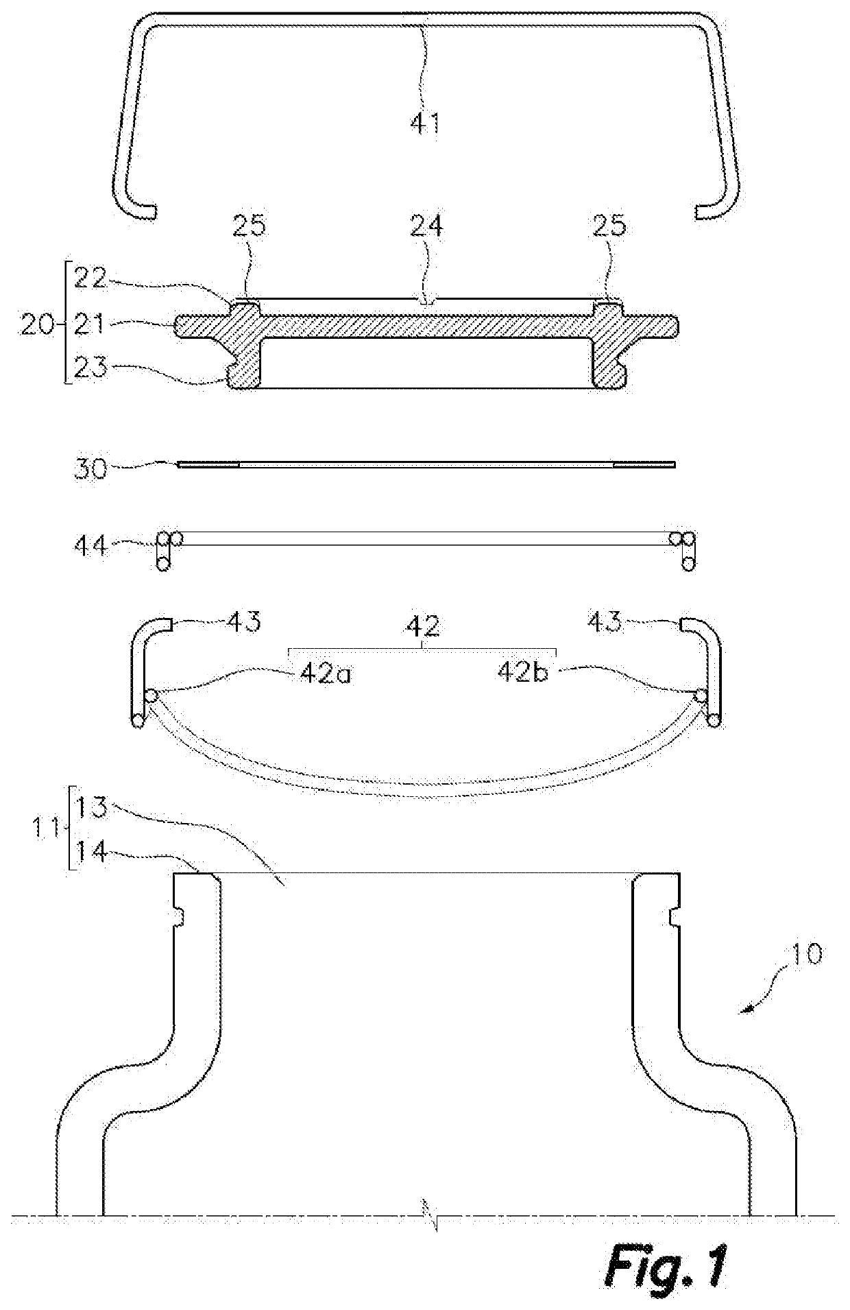
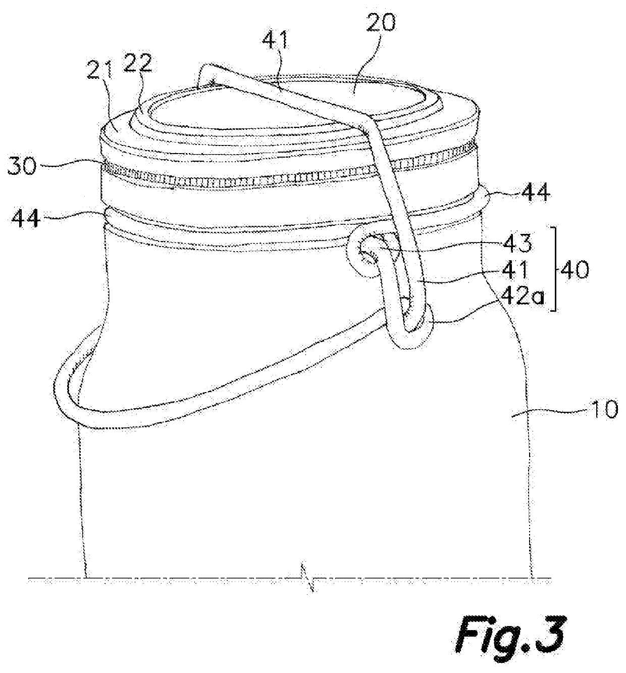
[0066]FIGS. 1, 2, and 3 show a container with a hermetic closure comprising a receptacle 10 which, in this example, is proposed to be a glass receptacle 10. Said receptacle 10 is provided with a cylindrical mouth 11 to which there is coupled a lid 20, also preferably made of glass, with a sealing ring 30 interposed to assure a leak-tight sealing between the mouth 11 and the lid 20.

[0067]The mouth 11 includes a receptacle opening 13 and an annular mouth surface 14 surrounding said receptacle opening 13.

[0068]It will be understood that although the preferred embodiment is made of glass, both the receptacle 10 and the lid 20 can be made of other materials, such as ceramic, for example, or the use of plastic is even optionally contemplated.

[0069]The lid 20 is a flat lid formed by a flat circular glass about 5 mm thick, defining a front side oriented upwards and a back side oriented downwards ...


PUM


Abstract

The container with a hermetic closure has a receptacle having a receptacle opening surrounded by an annular mouth surface, a lid having a front side and a back side intended for being oriented towards the outside and the inside of the receptacle, respectively, a sealing ring arranged between the annular mouth surface of the receptacle and an annular perimetral flange of the lid, and a closure mechanism formed by a shaped metal wire defining a first region coupleable to the lid, a second region being under elastic stress in a closed position and a third region coupleable to the receptacle. The front side of the lid has at least two opposite supporting points in an area coinciding with or adjacent to the annular flange, and the first region of the closure mechanism is configured for being supported, in a closed position, on said at least two opposite supporting points.

Description

TECHNICAL FIELD[0001]The present invention relates to the field of containers with a hermetic closure, the containers being of the type including a receptacle, a lid, a sealing ring and a closure mechanism formed by a shaped metal wire.STATE OF THE ART[0002]Containers provided with a lid held against the mouth of a receptacle by means of a closure mechanism formed by a shaped metal wire, with a sealing ring being sandwiched between the lid and the mouth of the receptacle to assure leak-tight closure, have been known for over a hundred years.[0003]Closure mechanisms can be found in many designs, with a well-known one being a mechanism similar, for example, to that described in document GB143520A which is provided with an arcuate metal wire that goes above the lid and presses it towards the receptacle at the center thereof, the lid having a dome shape with a rib in the center thereof on which said metal wire is supported. Lever mechanisms on opposite sides of the receptacle, also form...

Claims


Application Information

Patent Timeline
Patent Type & Authority Applications(United States)
IPC IPC(8): B65D45/06B65D45/30B65D53/02
CPCB65D45/06B65D2543/00296B65D45/305B65D2543/00305B65D53/02
Inventor BOTTGER, BETTINA
Owner BOTTGER BETTINA
Why Eureka
Try Eureka