Transmission with friction launch mechanism

a technology of friction launch mechanism and transmission mechanism, which is applied in mechanical equipment, transportation and packaging, and gearing. it can solve the problems of slipping device, loss reduction, and high efficiency loss at vehicle launch, and achieve the effect of improving the friction launch mechanism

Inactive Publication Date: 2006-05-30
GM GLOBAL TECH OPERATIONS LLC
View PDF38 Cites 45 Cited by
  • Summary
  • Abstract
  • Description
  • Claims
  • Application Information

AI Technical Summary

Problems solved by technology

As is well-known, the torque converter is a slipping device that has a high efficiency loss at vehicle launch.
This loss decreases, but continues, as the torque converter approaches a 1.0 to 1.0 speed ratio at high speed and low torque.
There is only slight axial space saving and perhaps more complex control features.

Method used


Image

  • Transmission with friction launch mechanism
  • Transmission with friction launch mechanism
  • Transmission with friction launch mechanism

Examples


Embodiment Construction

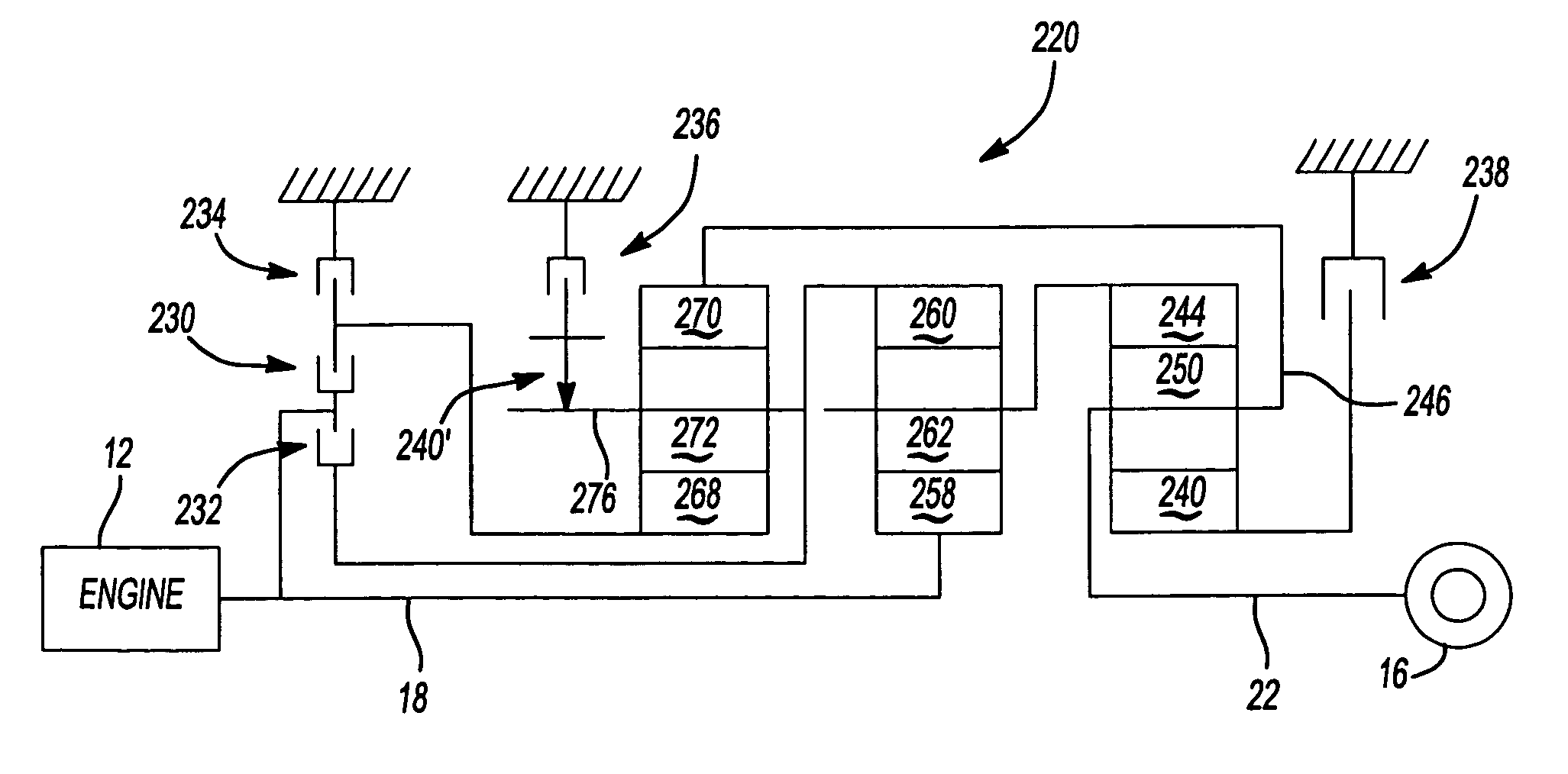
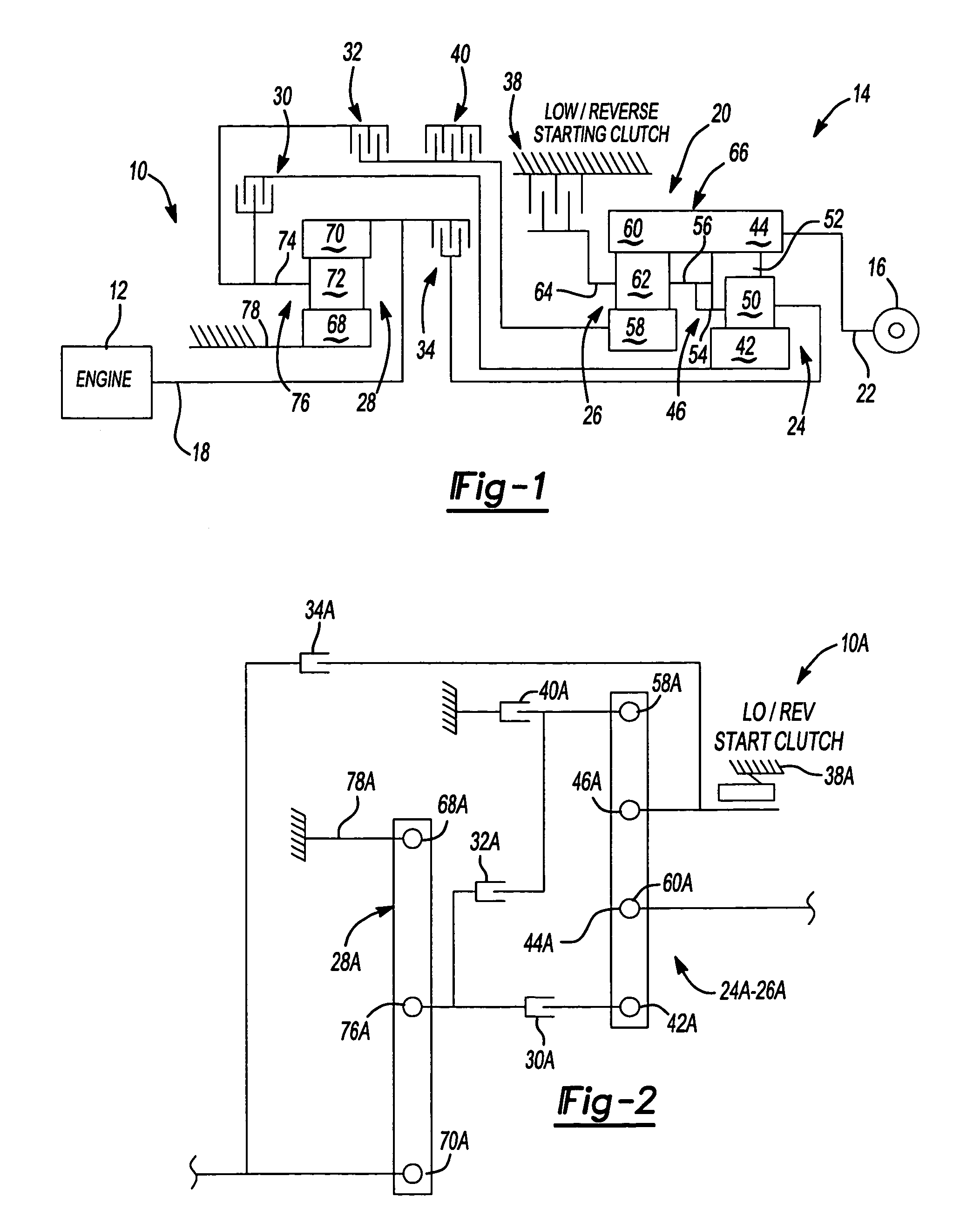
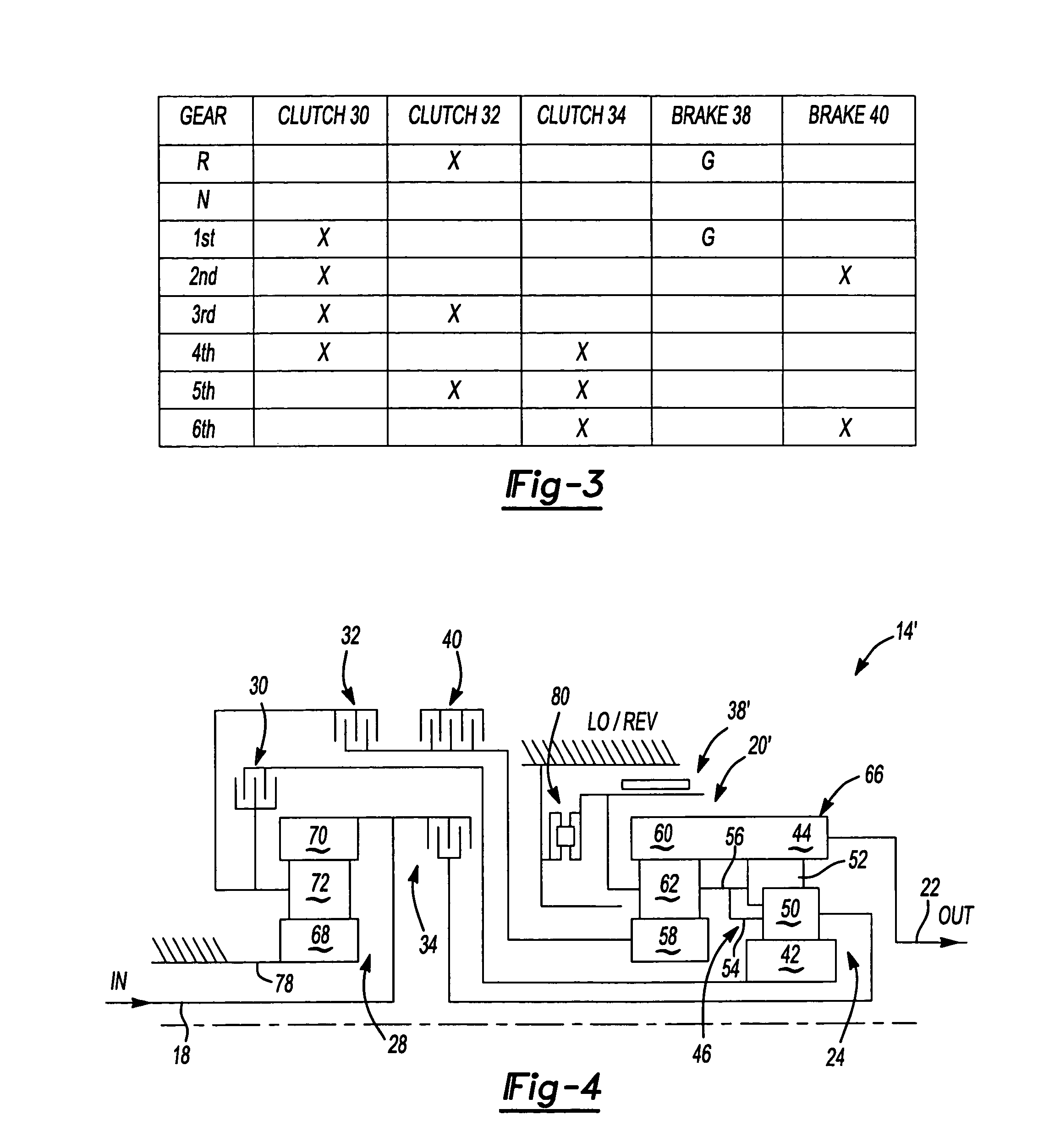
[0022]A powertrain 10 has a power source, such as a conventional internal combustion engine 12, a multi-speed planetary transmission 14, and a conventional final drive mechanism 16. Planetary transmission 14 includes an input shaft 18 connected directly with engine 12, a multi-speed planetary gear arrangement 20, and an output shaft 22 connected directly with final drive mechanism 16. Planetary gear arrangement 20 includes a compound planetary gearset 24, two simple planetary gearsets 26 and 28, three selectively engageable rotating torque transmitting mechanisms 30, 32 and 34 and two selectively engageable stationary torque transmitting mechanisms 38 and 40.

[0023]The rotating torque transmitting mechanisms 30, 32 and 34 are conventional fluid-operated multi-plate clutch assemblies, the construction of which is well-known in the art of power transmissions. Likewise, the stationary torque transmitting mechanisms 38 and 40 are conventional fluid-operated brake assemblies of either fri...


PUM


Abstract

A powertrain includes a power transmission having an input shaft continuously connected directly between an engine and a planetary gear member of a first planetary gearset. Another member of the planetary gearset is selectively grounded by a torque transmitting mechanism to establish a reaction member during the launch of a vehicle incorporating the powertrain. The reaction member is established during both the lowest forward drive ratio and the reverse drive ratio. A third member of the planetary gearset transmits the torque from the input shaft, as modified by the planetary gearset, to other planetary gearsets in down stream power flow arrangement with the first planetary gearset.

Description

CROSS-REFERENCE TO RELATED APPLICATIONS[0001]This application is a divisional of U.S. patent application Ser. No. 10 / 295,120 filed Nov. 15, 2002 now U.S. Pat. No. 6,827,664 that claims the benefit of U.S. Provisional Application Ser. No. 60 / 336,126, filed Nov. 15, 2001. The entire disclosure of Ser. No. 60 / 336,126 is incorporated by reference.FIELD OF THE INVENTION[0002]This invention relates to automatic shifting power transmissions and more particularly to power transmissions having a single torque transmitter operable to be selectively actuated to launch both forward and reverse drives.BACKGROUND OF THE INVENTION[0003]In automatic shifting power transmissions it is common practice to install a hydrodynamic fluid drive, such as a torque converter, between the power source (engine) and a multi-speed gear configuration, such as a planetary gear arrangement. The torque converter provides a torque multiplier between the engine and the gearing to improve the vehicle launch performance....

Claims


Application Information

Patent Timeline
Patent Type & Authority Patents(United States)
IPC IPC(8): F16H3/62F16H3/66
CPCF16H3/66F16H3/666F16H2200/2097F16H2200/2007F16H2200/201F16H2200/0052
Inventor STEVENSON, PAUL DWITTKOPP, SCOTT HWINSHIP, RICHARD ABORGERSON, JAMES B.MAGUIRE, JOEL M.KIENZLE, KENT H.DUSENBERRY, DONALD L.BIALLAS, JEFFREY J.CAREY, CLINTON E.
Owner GM GLOBAL TECH OPERATIONS LLC
Why Eureka
Try Eureka