Decorative tree lamp

a technology of decorative tree and lamp, which is applied in the field of decorative tree, can solve the problems of troublesome and monotonous, and achieve the effects of reducing volume, improving the defects of conventional products, and convenient transportation

Inactive Publication Date: 2006-06-06
WU JENG SHYONG
View PDF15 Cites 52 Cited by
  • Summary
  • Abstract
  • Description
  • Claims
  • Application Information

AI Technical Summary

Benefits of technology

[0003]The present invention allows a conventional Christmas light string to be easily transported and presents an improvement in the defects of the conventional products. The present invention relates to the use of a kind of decorative tree lamp, including a long trunk to be composed of many short pipes, the height of tree lamp can be adjusted by the use of a number of short pipes. These short pipes on the long trunk are provided with one or more connecting rings to connect with many branches. A base frame is used as a supporting surface to erect the base frame and has a center axle to support the long trunk so as to stand up right straight. Multiple branches connect one end with the connecting ring on the short pipe so as to use the connecting ring as the base point. The other end of the branch is used as the center of the trunk to be able to stretch out to form a tree shape. This may also be folded up to reduce the volume. Single or multiple sets of light strings, composed of many lamp bulbs, lamp holders, electrical conductors and receptacles are used with a fixing device to fix them on the branches to establish tree light strings.
[0015]The present invention relates to the decorative tree lamp and the lamp holder of the light string being cylinder, said lamp holder is connected with electrical conductor. After the fixing device is to fix with electrical conductor, the decorative tree lamp can be suspended freely in the air as needed.
[0021]The present invention relates to the decorative tree lamp and the light string having an attached protection device, transformer or functional control device to increase the decoration functionality.

Problems solved by technology

This can be troublesome and monotonous.

Method used


Image

  • Decorative tree lamp
  • Decorative tree lamp
  • Decorative tree lamp

Examples


Embodiment Construction

[0038]Referring to the drawings in particular, for the convenience of the description, the same parts are designated by the same number in the drawings.

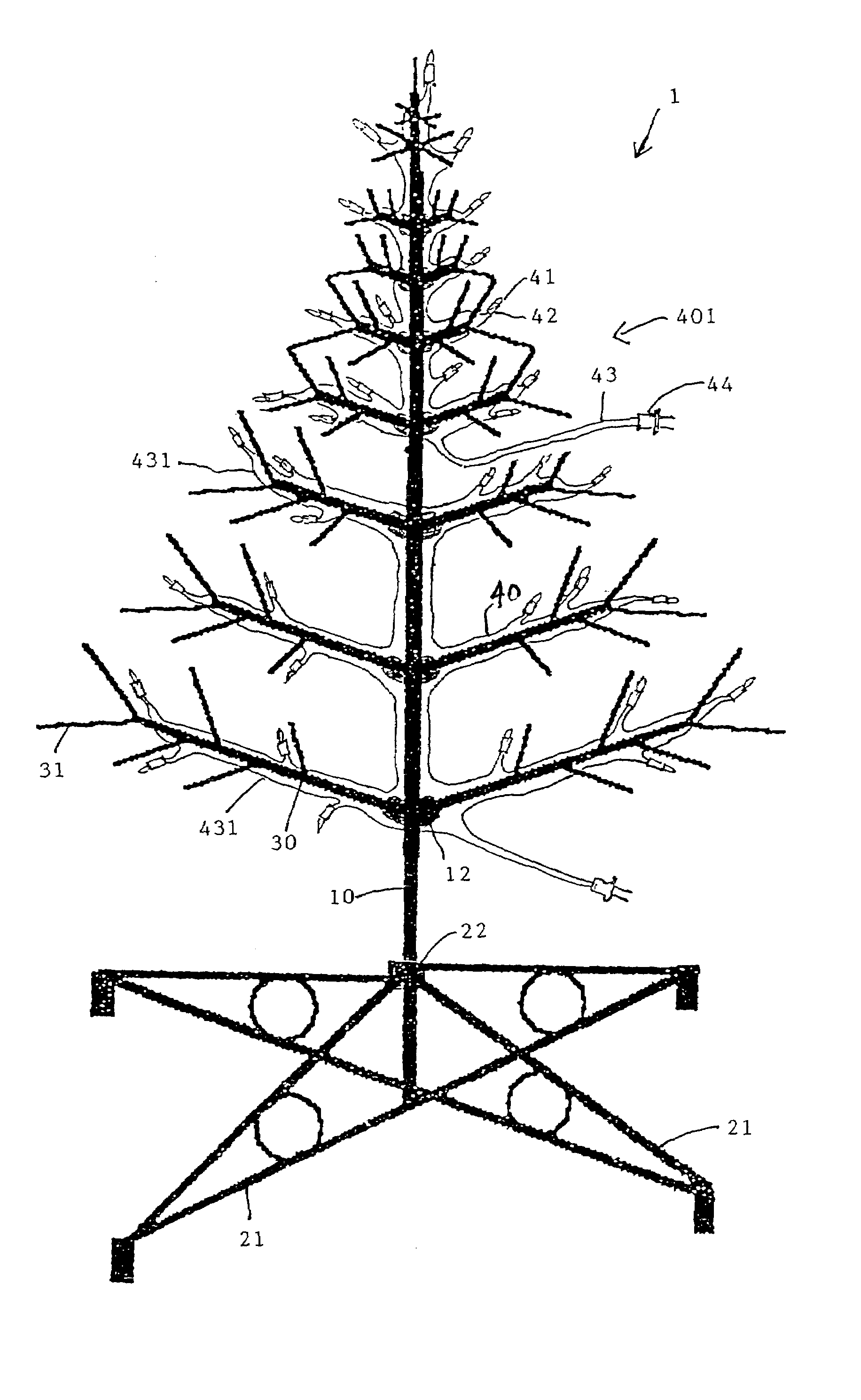
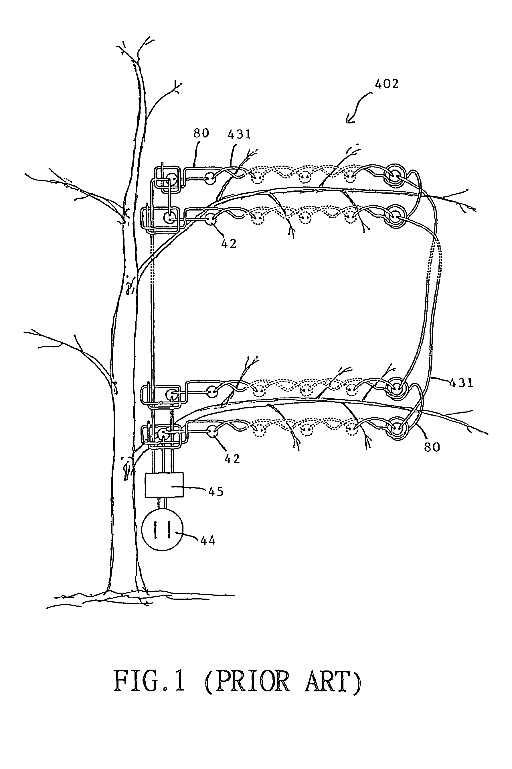
[0039]Referring to FIG. 1, a conventional light string is shown in a perspective view. The conventional light string includes an electrical conductor used to connect lamp holder 42 and lamp bulb 41. The structure is formed by using serial or serial-parallel connections. The single electrical conductor 431 or many electrical conductors are used to form a single loop or a multiple loop 402. The loop 402 is attached with non-electrical connector 80. The receptacle 44 connects with a light string and a power supply. Between the receptacle 44 and the lamp holder 42, a protected device, a transformer or a functional control device 45 are attached. The lamp holder attached with a hook trough is used to hang the electrical conductor 431 and non-electrical connector 80, then to hang on the tree to establish decorative tree lamp.
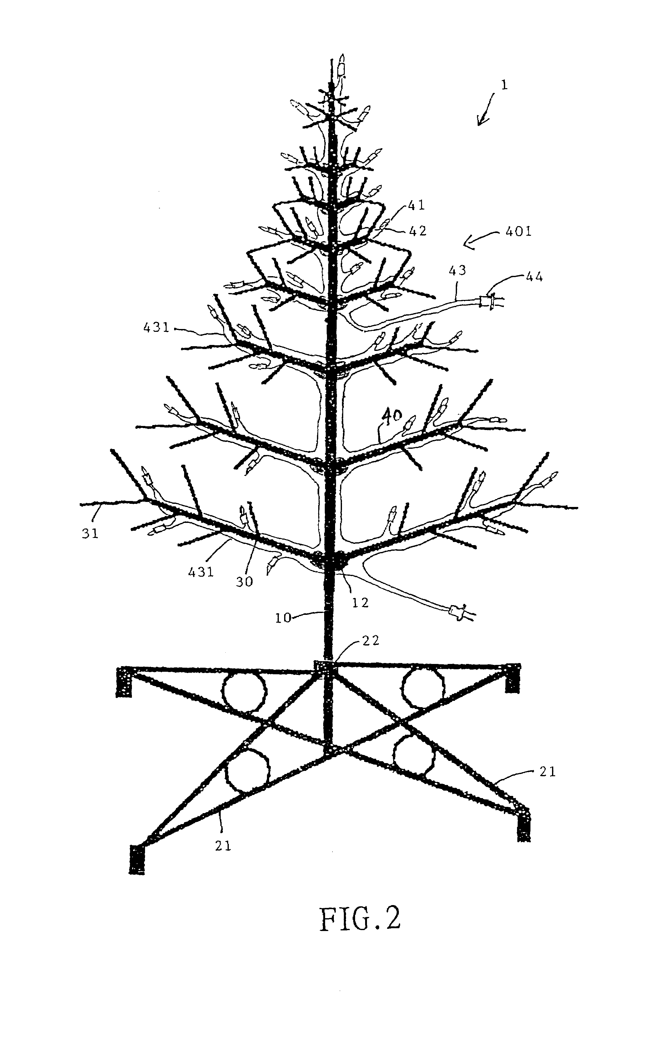
[0040]FIG. 2 i...


PUM


Abstract

A decorative tree lamp includes a long trunk composed of many short pipes. The height of the tree lamp can be adjusted based on the number of the short pipes used. At least one of the short pipes that form the long trunk is provided with one or more connecting rings to connect with many branches. A base frame is used as a supporting surface and has a center axial receiving part to support the long trunk so that it stands up right and straight. Multiple branches connect one end with the connecting ring on the short pipe and use the connecting ring as the base point. The other end of the branch extends away from the center of the trunk to be able to stretch out to form a tree shape and to also be able to be folded up to reduce the volume. One of single or multiple sets of light strings are provided, composed of many lamp bulbs, lamp holders, electrical conductors and receptacles. A fixing device is used to fix the light strings on the branches to establish tree light strings.

Description

FIELD OF THE INVENTION[0001]The invention relates to a decorative tree with included lights forming a decorative tree lamp.BACKGROUND OF THE INVENTION[0002]A conventional lamp light string set providing a Christmas light string includes a lamp bulb, lamp base, lamp holder, multiple electrical conductors, and receptacles or a flasher control. The electrical conductors can be single or double or more than two wound into an electrical circuit. The distributed conductors can be formed in one, two or more than two electrical conductors, such as shown in FIG. 4 of U.S. Pat. No. 4,241,387 and the attached FIGS. 1 and 2 (the prior art) in this case. In general, such electrical conductors are wound on trees. This can be troublesome and monotonous. Further, such work must be repeated over several years. The present invention provides an improvement that addresses the defects of the conventional products. The present invention also involves the use of artificial tree trunks and tree branches t...

Claims


Application Information

Patent Timeline
Patent Type & Authority Patents(United States)
IPC IPC(8): F21S6/00F21S4/00
CPCF21S4/001F21S4/10
Inventor WU, JENG-SHYONG
Owner WU JENG SHYONG
Why Eureka
Try Eureka