Traffic cone (2)

Inactive Publication Date: 2006-06-06
KUO WEN NAN
View PDF15 Cites 43 Cited by
  • Summary
  • Abstract
  • Description
  • Claims
  • Application Information

AI Technical Summary

Benefits of technology

[0014]4. The base is very heavy to have its gravity center located therein, letti

Problems solved by technology

The conventional traffic cones described above are all composed of a cone body and a base separately made and then assembled together, having a common drawback that the base and the cone body may often beco

Method used


Image

  • Traffic cone (2)
  • Traffic cone (2)
  • Traffic cone (2)

Examples


Embodiment Construction

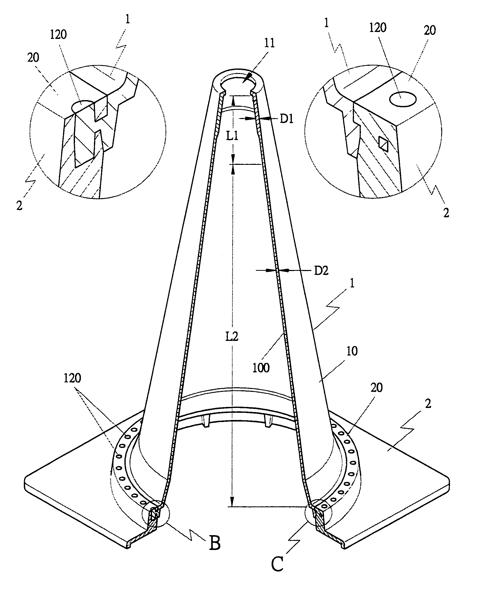
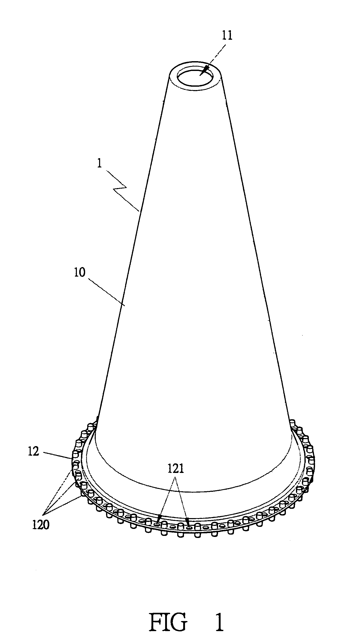
[0028]A first embodiment of a traffic cone in the present invention, as shown in FIGS. 1 to 6, includes a cone-shaped body 1 and a base 2 as main compoments combined together.

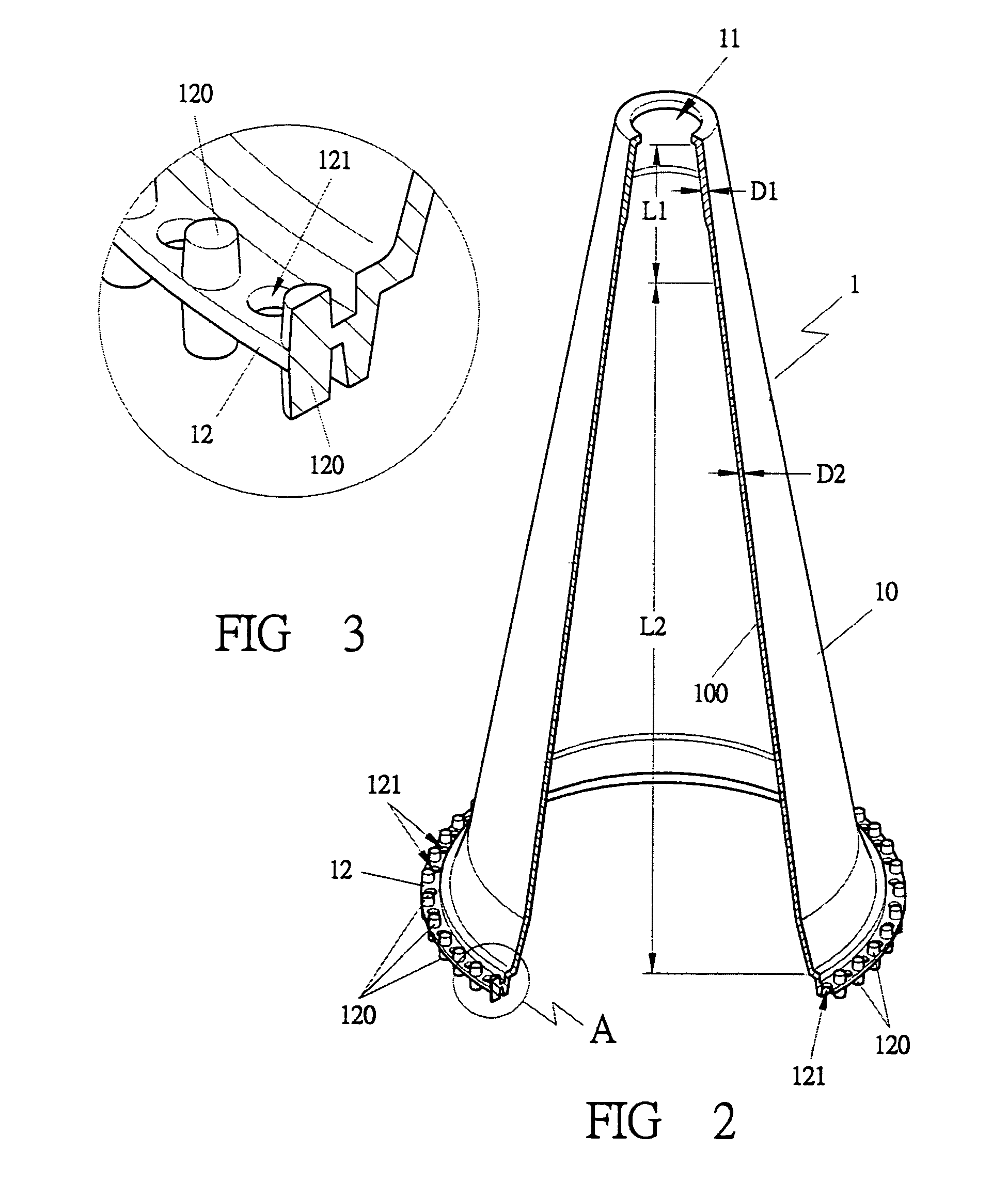
[0029]The cone-shaped body 1 has a tapered-up outer surface 10, a hole 11 formed in the top for inserting a warning flag, a warning light or the like, an L1 portion of the wall 100 having a thickness D1 larger than that D2 of an L2 portion of the wall 100 as shown in FIG. 2, and a connecting circumference 12 formed in a lower end and provided with many upright bars 120 extending up and down the connecting circumference 12 and spaced apart equidistantly with a through hole 121 formed between every two neighboring bars 120 as shown in FIG. 3.

[0030]The objective of the provision of the different thickness for the L1 and the L2 portion of the wall 100 is for convenience of stacking a number of the traffic cones, because the L1 portion of an upper traffic cone can have a gap (S) between its inner surface and an oute...


PUM


Abstract

A traffic cone includes a cone-shaped body and a base. The cone-shaped body has a hole in the top and a connecting circumference formed in a lower end. The connecting circumference is provided with a large number of upright bars spaced apart equidistantly, and a through hole formed between every two neighboring bars. The base is formed in a mold that an already formed cone-shaped body is placed in advance before the base is formed so the base may be combined integral with the cone-shaped body after the base is finished. Then the base completely wraps around and hides the connecting circumference of the cone-shape body, with the through holes of the connecting circumference filled up totally by the base.

Description

BACKGROUND OF THE INVENTION[0001]1. Field of the Invention[0002]This invention relates to a traffic cone, particularly to one consisting of a cone-shaped body and a base separately formed to have different colors and then assembled together, taking the advantage of a U.S. patent application Ser. No. 10 / 917,100 and simplifying the advantages for practicality. When the traffic cone is hit or run over by a vehicle accidentally, the base can be automatically separated from the cone-shaped body, preventing the traffic cone from getting stuck with the chassis of the vehicle so as to safeguard traffic safety.[0003]2. Description of the Prior Art[0004]A conventional traffic cone or traffic delineator disclosed in a U.S. patent Ser. No. 6,014,941 is composed of a cylinder and a base, and the base has a hole for the cylinder to pass through so as to let the traffic cone stand on the ground, with a handle fixed on the top of the cylinder for holding to carry the traffic delineator around. Furt...

Claims


Application Information

Patent Timeline
IPC IPC(8): E01F9/012
CPCE01F9/0122E01F9/688E01F9/654
Inventor KUO, WEN-NAN
Owner KUO WEN NAN
Why Eureka
Try Eureka