
Optical microscope with modifiable lighting and operating process of such a microscope

a microscope and optical technology, applied in the field of optical microscopes, can solve the problems of increasing the cost of experimental devices, affecting the fluorescence of bio-active spots, and difficulty in simultaneously identifying strong luminous and weak luminous zones of one and the same chip

Inactive Publication Date: 2006-06-20
COMMISSARIAT A LENERGIE ATOMIQUE ET AUX ENERGIES ALTERNATIVES
View PDF11 Cites 4 Cited by
  • Summary
  • Abstract
  • Description
  • Claims
  • Application Information

AI Technical Summary

Problems solved by technology

Observation by optical microscope (reading) of DNA chips, more particularly those presenting a strong contrast, requires suitable lighting techniques—it is in fact difficult to simultaneously image strongly luminous and weakly luminous zones of one and the same chip due to the limited range of the detectors.
Thus, measurement of the fluorescence of the bio-active spots is impaired by the fluorescence of the zones surrounding the bio-active spots.
When measurement of reaction kinetics is concerned, prolonged lighting of certain zones may destroy the fluorescence, thus leading to disturbance of the results.
These solutions impose constraints which increase the cost of the experimental devices and which are not applicable in all cases.
This solution presents limitations (non-linear response of the detector or low efficiency of the anti-glare system) and does not provide a solution to the problems relating to light diffraction by the collection optics, a phenomenon which spreads the light energy from the intense regions into the weakly luminous regions.
This solution is unsuitable when reading must be performed at the bottom of the wells as is the case for microplates or certain DNA chips, as the edges of the wells reduce the size of the light beam and therefore the efficiency of measurement at the level of the well bottoms.
The mechanical and electronic components necessary to perform scanning are expensive and difficult to implement.

Method used


Image

  • Optical microscope with modifiable lighting and operating process of such a microscope
  • Optical microscope with modifiable lighting and operating process of such a microscope
  • Optical microscope with modifiable lighting and operating process of such a microscope

Examples


Embodiment Construction

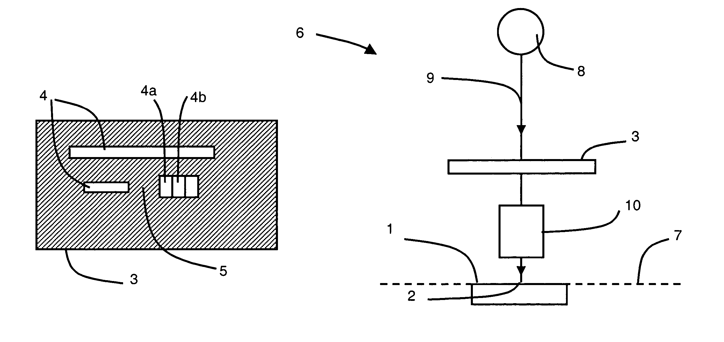
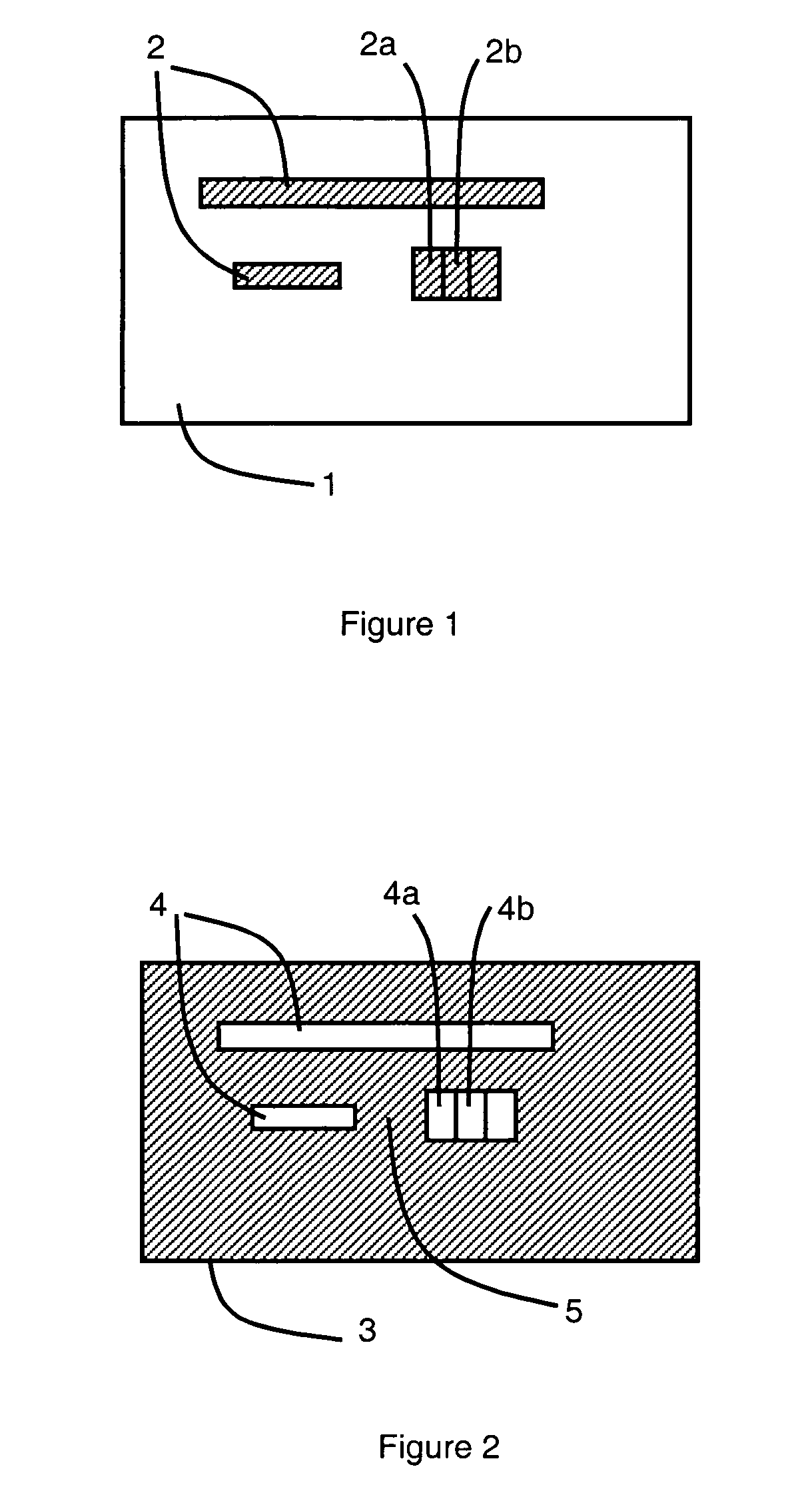
[0021]FIGS. 1 and 2 respectively represent an object 1 comprising several spots 2 to be observed by means of an optical microscope and a modifiable optical transmission screen 3 comprising zones each presenting a first passing state and a second closed state. In FIG. 2, zones 4 represent passing zones and zones 5 represent closed zones.

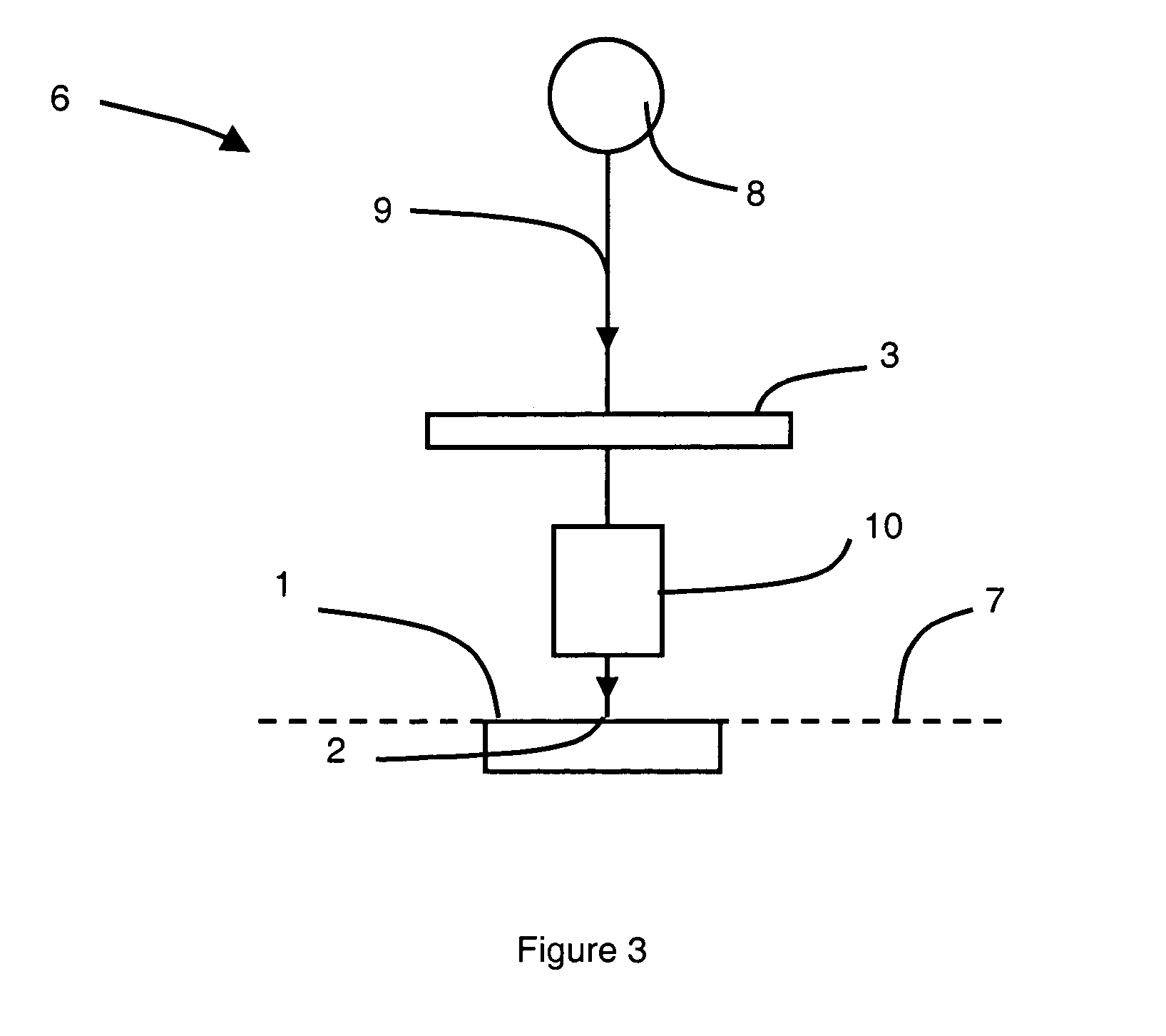
[0022]FIG. 3 represents an embodiment of an optical microscope 6 suitable for observing several spots 2 of an object 1 placed in an object plane 7 of the microscope 6, comprising a light source 8 and a light beam coming from the light source 8 and passing along an optical path 9. A modifiable optical transmission screen 3 is placed on the optical path 9. The screen 3 is designed to generate an image in the object plane 7, the image coinciding substantially with the spots 2 of the object 1. An objective 10, arranged between the screen 3 and the object 1, enables the object 1 to be observed. In FIG. 3, the optical transmission screen 3 transmits light b...


PUM

PropertyMeasurementUnit
optical microscopeaaaaaaaaaa
structureaaaaaaaaaa
transparentaaaaaaaaaa

Abstract

An optical microscope is adapted for observation of several spots of an object by a modifiable optical transmission screen placed on the path of the optical beam and able to generate in the object plane a screen image coinciding substantially with the spots of the object. The modifiable optical transmission screen can comprise a matrix of mirrors, each of the mirrors presenting a first position enabling the light beam to be reflected to the object along the optical path and a second position enabling the light beam to be diverted from the optical path. Alternatively, the modifiable optical transmission screen can comprise a matrix of liquid crystal elements, each of the liquid crystal elements presenting a first transparent state, a second opaque state and, possibly, a third polarising state. The light source can be a light-emitting diode array.

Description

BACKGROUND OF THE INVENTION[0001]The invention relates to an optical microscope suitable for observation of several spots of an object placed in an object plane of the microscope, comprising a light source, an objective and a light beam coming from the light source.STATE OF THE ART[0002]Observation by optical microscope (reading) of DNA chips, more particularly those presenting a strong contrast, requires suitable lighting techniques—it is in fact difficult to simultaneously image strongly luminous and weakly luminous zones of one and the same chip due to the limited range of the detectors. Either the detector amplification is sufficient to visualise the weakly luminous zones and the strongly luminous zones are saturated, or the detector amplification is correct for the strongly luminous zones and too weak to distinguish the weakly luminous zones from the background noise.[0003]Examples of strongly contrasted objects are immuno-fluorescence blades whose bio-active spots presenting a...

Claims


Application Information

Patent Timeline
Patent Type & Authority Patents(United States)
IPC IPC(8): G02B21/06G02B21/00G02F1/13
CPCG02B21/06
Inventor BOUTET, JEROMEPERRAUT, FRANCOISPELTIE, PHILIPPERIZO, PHILIPPE
Owner COMMISSARIAT A LENERGIE ATOMIQUE ET AUX ENERGIES ALTERNATIVES
Learn More