Display device

a display device and display technology, applied in the field of display devices, can solve the problems of reducing the contrast ratio, deteriorating image quality, and darkening the displaying of images,

Inactive Publication Date: 2006-06-27
SAMSUNG DISPLAY CO LTD +1
View PDF23 Cites 123 Cited by
  • Summary
  • Abstract
  • Description
  • Claims
  • Application Information

AI Technical Summary

Problems solved by technology

In such a configuration as described above, since the reflective electrode is in a state of mirror having a high reflectance when the OLED display device is in the state where it emits no light, under a bright environment, the image quality is deteriorated due to the fact that surrounding backgrounds are reflected in the reflective electrode and the image which should be displayed in black is not becomes dark, reducing a contrast ratio.
These lead to problems, which should be solved.
However, the OLED display device having a circular polarizer plate is disadvantageous in the fact that the displaying of the images are darkened since parts of lights emitting from the emissive layer are absorbed on the circular polarizer plate.
However, in the case of using the later OLED display device under a bright ambient condition, there arises the following problems associated with ambient lights, which will enter in the later OLED display device: The ambient lights entering in the OLED display device are generally un-polarized lights and at least halves of them are adsorbed on the polarizer plate, when they are passed through the polarizer plate.
This means that an unnecessary reflection of the ambient light is increased by the arrangement of the cholesteric liquid crystal layer and, thus, indicates that the black image cannot be displayed in a sufficient manner under a bright condition, leading to markedly decreasing of the contrast ratio.
These conditions are the conditions where the unnecessary reflection of the ambient light brought about by placing the cholesteric liquid crystal layers becomes large, and thus, lead to a remarkable decrease in the contrast ratio under a bright condition.
However, since the existing organic light-emitting diodes have the wavelength of the light emission deviating from the desirable wavelength or since the distribution of the wavelength for light emission is wide and gentle, no sufficient color reproduction can be obtained.
Also, since the luminous efficiency (lm / W) is differed in the colors, the power consumption for displaying white becomes large.
At the present situation, the organic light-emitting diode for green light emission has the highest luminous efficiency, but since the balance of chromaticity of each color is bad, it is required that the luminous intensity of the organic light-emitting diode for green light emission, which has a high luminous efficiency is relatively decreased, and the luminous intensities of the organic light-emitting diodes for red and blue light emission are increased, leading to decreased total efficiency.

Method used


Image

  • Display device
  • Display device
  • Display device

Examples


Embodiment Construction

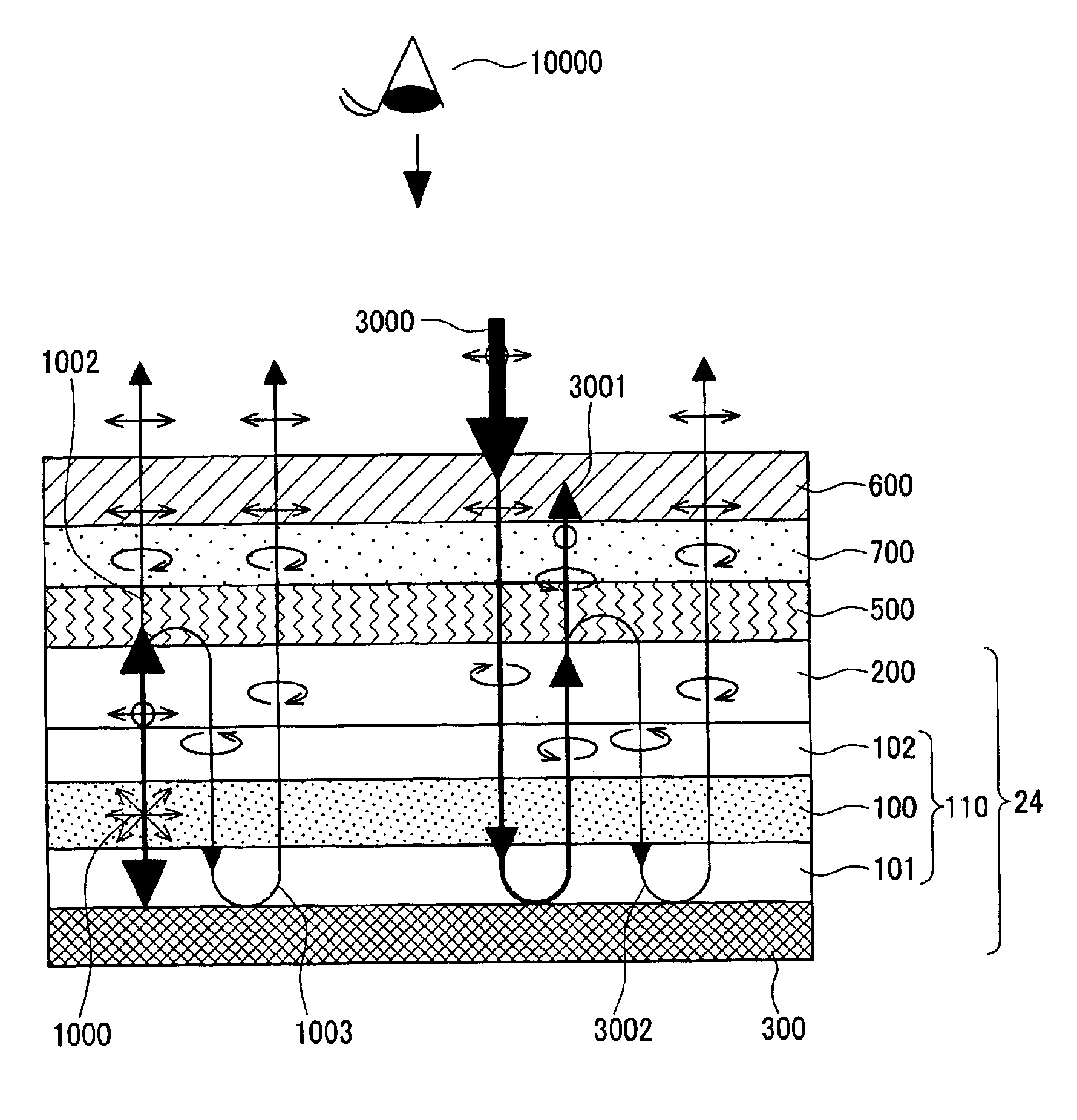
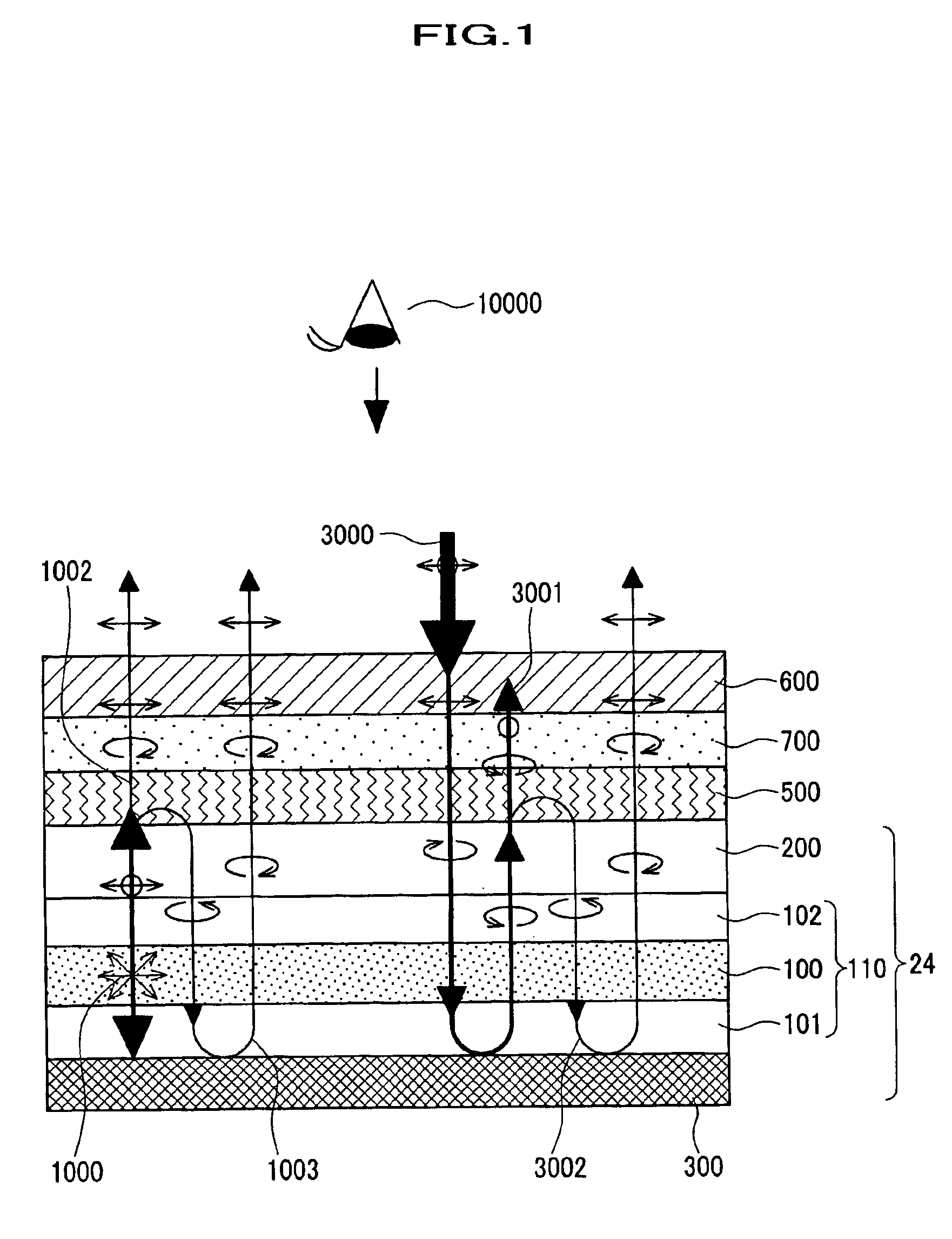
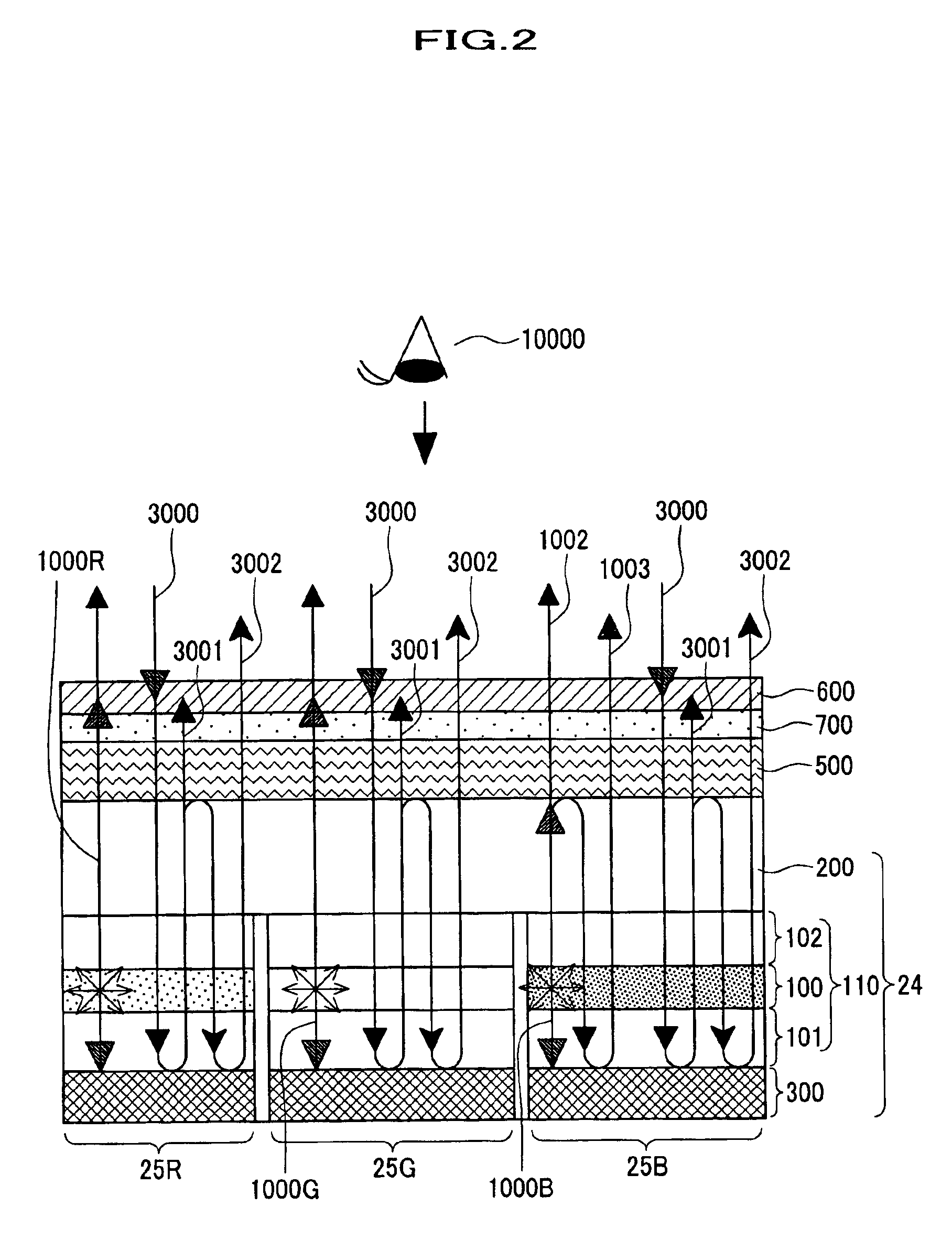
[0062]The present invention will now be described by referring to the drawings. FIG. 1 is a partially cross-sectional view showing a schematic configuration for explaining the basic configuration and the operation principal of the display device according to the present invention. FIG. 2 is a partially cross-sectional view showing a schematic configuration for explaining the basic configuration and the operation principal of the display device according to the present invention, which displays full color images.

[0063]First, referring to FIG. 1, the basic configuration and the operation principal of the display device according to the present invention will be described.

[0064]A light emitting device part according to the display device of the present invention is composed of an organic light emitting diode 24 comprising a transparent electrode 200 serving as an anode formed on the substrate (not shown), a reflective electrode 300 serving as a cathode and as a specular reflector, an o...


PUM


Abstract

A display device of the present invention has light-emitting devices making up a plurality of pixels placed in a matrix form. In the display device of the present invention, the light-emitting devices each possesses an emissive layer and a reflective element placed on the rear surface of the emissive layer; the emissive layer possesses at the said of the front side, a polarization separator which separates the light emitted from the emissive layer into two kinds of polarized components by the reflection and the transmission, and phase plate; the emissive layer substantially maintains the sate of the polarization of the light transmitted there-through; the reflective element at least reflects the circularly polarized light impinging in the vertical direction mainly as a circularly polarized light having a reverse helicity direction; and the polarization separator has a reflectance of the wavelength range from 520 nm to 600 nm smaller than a reflectance of range not more than 540 nm.

Description

BACKGROUND OF THE INVENTION[0001]1. Field of the Invention[0002]The present invention relates to a display device, which controls the operations of light emitting devices for display. More particularly, the invention relates to a technique available for light emitting devices such as organic light emitting diodes comprising a emissive layer having a reflective element provided on the rear surface thereof and a display device possessing such light emitting devices.[0003]2. Description of the Related Arts[0004]Organic light emitting diodes elements (devices) which emits a light by injecting holes and electrons into a emissive layer to thereby convert an electric energy into a light energy. Such types of display devices (hereinafter sometimes abbreviated as “OLED display devices”), which is emission type ones, have a characterized to have a thin type and a light weight unlike non-emissive type ones represented by liquid crystal devices. Furthermore, OLED display devices are characteriz...

Claims


Application Information

Patent Timeline
Patent Type & Authority Patents(United States)
IPC IPC(8): G09G3/10G02B5/30G09F9/00H01L27/32H01L51/50H01L51/52H05B33/02H05B33/04H05B33/22H05B33/26
CPCG02B5/3016H05B33/22H01L51/5281H01L27/3211H01L27/3244H10K59/35H10K59/12H10K50/86
Inventor ADACHI, MASAYA
Owner SAMSUNG DISPLAY CO LTD
Why Eureka
Try Eureka