Nuclear-fueled power generating system

a technology of nuclear power generation and jet engines, applied in the direction of nuclear engineering problems, machines/engines, greenhouse gas reduction, etc., can solve the problems of multiple barriers to the continued operation of existing nuclear reactors, increase the cost of operating nuclear power generation stations, and reduce the overall electrical generation efficiency, etc., to achieve rapid and complete shutdown of jet engines

Inactive Publication Date: 2006-07-11
NUGEN LLC
View PDF15 Cites 11 Cited by
  • Summary
  • Abstract
  • Description
  • Claims
  • Application Information

AI Technical Summary

Problems solved by technology

Both power generation systems include thermal energy losses which reduces the overall electrical generation efficiency.
Although many of these concerns are exaggerated, they have resulted in multiple barriers to the continued operation of existing nuclear reactors as well as the design, placement and construction of newer reactors.
Additionally, the safety concerns requires any operational nuclear reactor to adhere to a myriad of precautions and restrictions that are not found in other power generation systems such as coal which increases the cost of operating nuclear power generation stations.
Also, locations suitable for such large power generation facilities are extremely limited.
Internal combustion jet engines require a constant supply of extremely flammable jet fuel.
Additionally, the exhaust from conventional jet engines contain many substances that are harmful to the environment and contribute to air pollution.
Further, conventional jet engines are relatively inefficient in converting jet fuel to thrust energy.
Therefore, the use of such a power generating system for any period of time increases the demand on hydrocarbon fuels and results in an increase in air pollution.
Additionally, the power generating system has substantial energy losses due to the significant friction between the wheels and the track and between the hub and the shaft as well as the drag created by the ailerons moving through the air during operation.
Thrust created by the ram jets or the rocket motors causes the plate to rotate, which causes the shaft and generator to spin.
However, using volatile liquid fuel introduces an additional danger.
While the exhaust heat is used as a source for a secondary generator, the added equipment required to pump the water through the coolant jacket surrounding the fire chamber, into an associated coolant ring and through the turbine increases the losses experienced by the overall power generation system.

Method used


Image

  • Nuclear-fueled power generating system
  • Nuclear-fueled power generating system
  • Nuclear-fueled power generating system

Examples


Embodiment Construction

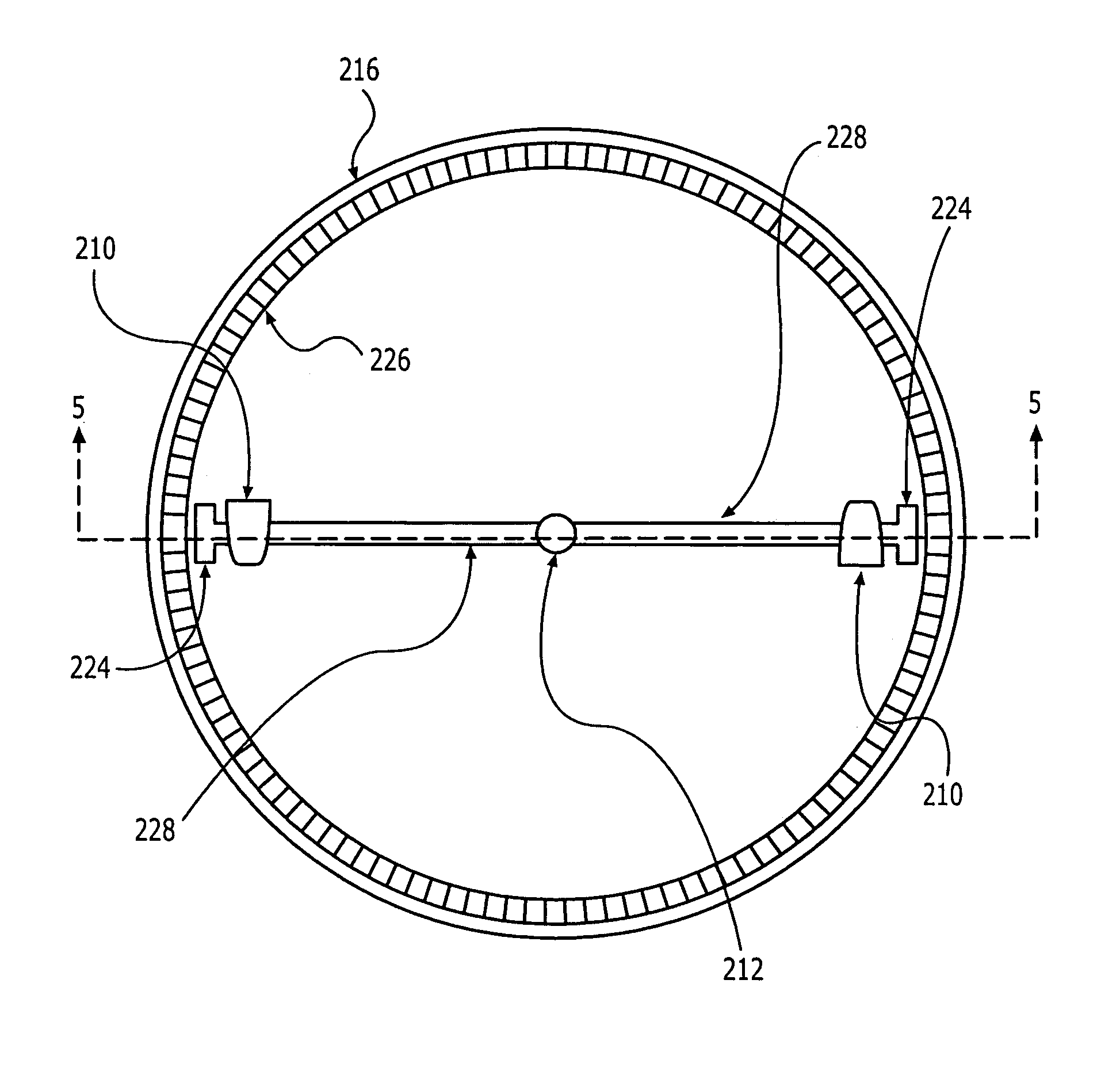
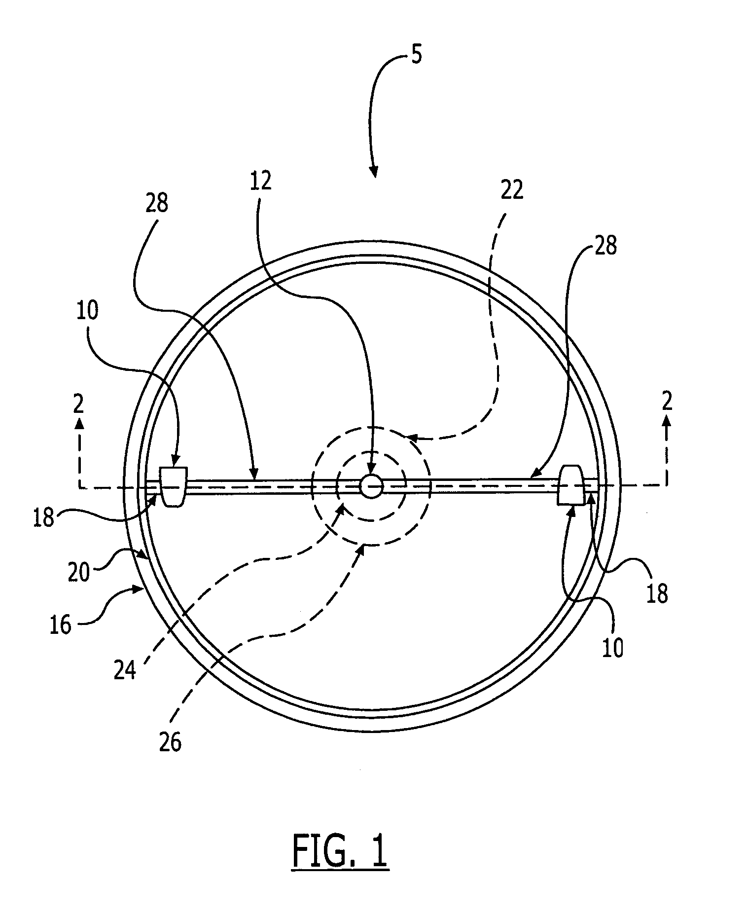
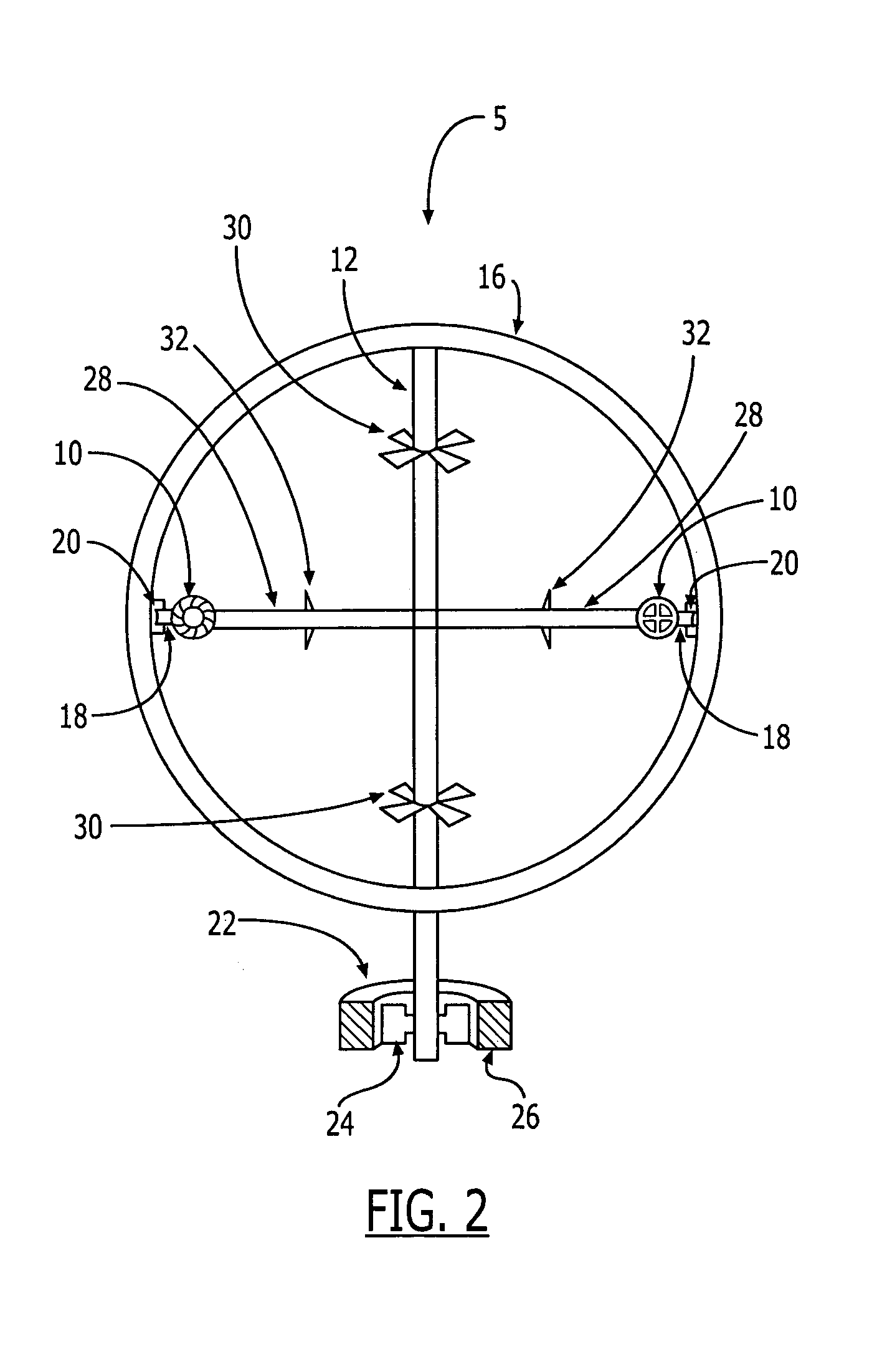
[0028]A power generating system 5, in accordance with a preferred embodiment of the present invention as shown in FIGS. 1 and 2, has two nuclear fueled jet turbine engines 10, attaching members 28, a rotatable central shaft 12, an apparatus for converting rotational motion to electricity 22, and a containment structure 16.

[0029]Each of the jet turbine engines 10 is attached to one end of each of the connecting members 28. A second end of each of the attaching members 28, opposite the engines 10, is attached to the central shaft at a first position on the central shaft 12 such that the connecting members 28 are aligned and diametrically opposed thereto. The engines 10 and the attaching members 28 are oriented such that thrust generated by the engines 10 is perpendicular to a longitudinal axis of the central shaft 12 thereby causing the central shaft 12 to rotate about the longitudinal axis of the central shaft 12 when the engines 10 are operating. The central shaft 12 and the connect...


PUM


Abstract

An apparatus for generating electricity that uses at least one jet-type engine fueled with fissile material. The nuclear fueled jet engine is affixed to a connecting member that projects from a central, rotatable shaft, which is in engageable communication with an apparatus for converting the rotation of the central shaft to electricity, such as a stator and rotor combination. The engine is positioned so that the thrust produced by the jet engine causes the engine and connecting member to travel in a radial direction around the longitudinal axis of the central shaft, rotating the central shaft. As the central shaft rotates, the rotational motion of the central shaft is transmitted to conversion apparatus. An operating gas is used to cool the nuclear fueled jet engines and as the propellant for the jet engines.

Description

[0001]This application is a divisional of prior application Ser. No. 10 / 244,187, filed on Sep. 16, 2002, now granted as U.S. Pat. No. 6,877,309, which claims the benefit of U.S. provisional application No. 60 / 323,506, filed Sep. 19, 2001, each of which is incorporated herein by reference in its entirety.FIELD OF THE INVENTION[0002]This invention relates to the production of electricity through the use of nuclear energy, in particular nuclear fueled jets.BACKGROUND OF THE INVENTION[0003]For almost fifty years, electricity has been generated by large-scale power plants utilizing nuclear reactors as the energy source to heat the coolant in the reactor that, directly or indirectly, drives a turbine that generates electricity. Fuel assemblies containing fissile material are placed within the reactor core in precise patterns. The coolant is pumped through the reactor core, where the heat generated by the individual fuel assemblies is transferred to the coolant. In one common commercial po...

Claims


Application Information

Patent Timeline
Patent Type & Authority Patents(United States)
IPC IPC(8): F02C3/14F02K11/00G21D5/02F02C1/05F02C3/16F02K99/00
CPCF02C1/05F02C3/165G21D5/02G21Y2004/40G21Y2002/201Y02E30/00
Inventor RHYNE, STEPHEN K.
Owner NUGEN LLC
Why Eureka
Try Eureka