Automated continuous haulage system

a technology of automatic control and continuous haulage, which is applied in the direction of distance measurement, instruments, and using reradiation, etc., can solve the problems of limited view of the mine wall nearest the cab, unsynchronized component advancement, and limited view of the mbc operator

Inactive Publication Date: 2006-07-11
CATERPILLAR GLOBAL MINING LLC +1
View PDF13 Cites 23 Cited by
  • Summary
  • Abstract
  • Description
  • Claims
  • Application Information

AI Technical Summary

Benefits of technology

[0010]It is therefore one object of the instant invention to provide a method and apparatus for detecting the position of an mobile bridge carrier. It is another object of the present invention to provide a method and apparatus for automatically raising and lower a conveyor in response to mine ceiling and floor conditions. It is another object of the present invention to provide a method and apparatus to determine the angle between a piggyback conveyor and at least one mobile bridge carrier. It is a further object of the invention to provide an apparatus and method for determining the movement of an individual mobile bridge carrier as well as a plurality of mobile bridge carriers and piggyback conveyors as part of a continuous haulage system. It is yet another object of the present invention to provide a method and apparatus for automating an complete continuous haulage system that encompasses previously listed objectives.

Problems solved by technology

In this manner, the linked components may advance in an unsynchronized fashion, however the MBC operator typically cannot see the MBC ahead or behind him, and only has a limited view of the piggyback conveyors linked to his MBC.
The MBC operator has only a limited view of the mine wall opposite the driver's cab, and his view of the mine wall nearest the cab is limited by lighting conditions and his close proximity to it.
Particularly with a long train of MBCs and piggyback carriers, the use of multiple human operations adds to higher overhead costs and increased opportunities for an injury to employee to occur.

Method used


Image

  • Automated continuous haulage system
  • Automated continuous haulage system
  • Automated continuous haulage system

Examples


Embodiment Construction

Mechanical Components

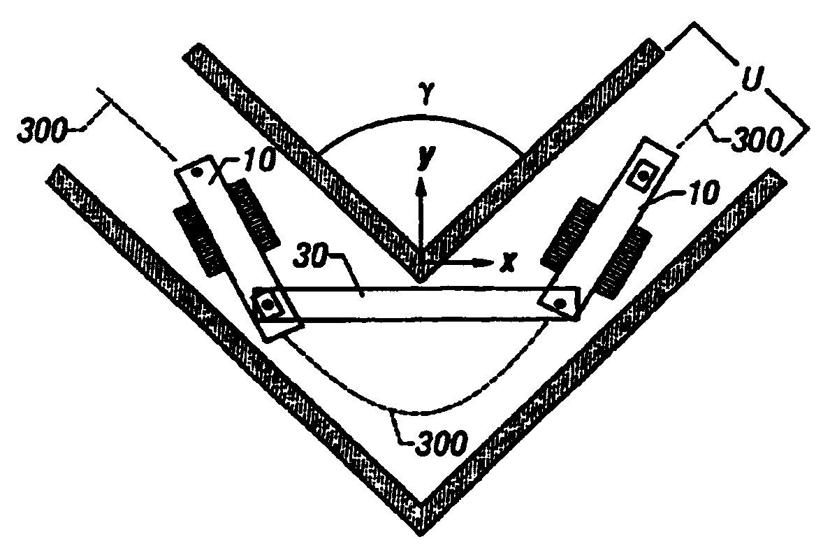
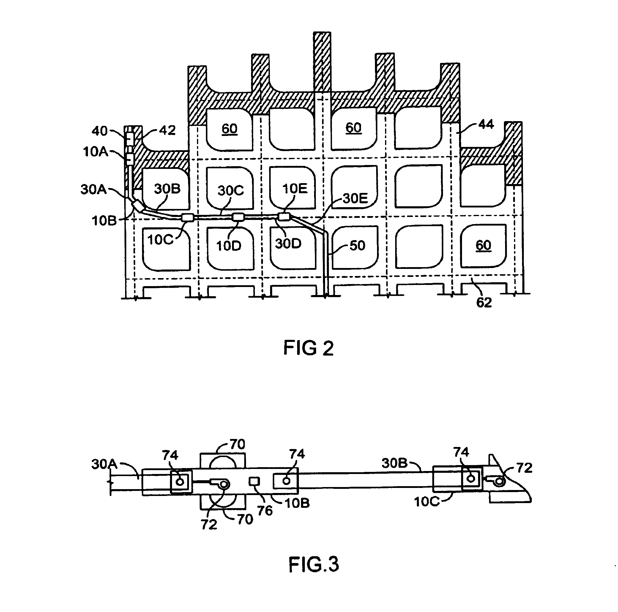
[0022]In the preferred embodiment, at least one pair of mobile bridge carrier (MBC) and piggyback conveyor (“Pigs”) units of a continuous haulage system are automated such that navigation through an underground mine can be accomplished with little or no operator input or intervention. In one embodiment, automation is accomplished through the use of a series of sensors mounted on each MBC and an electronic controller which receives data from the respective sensors, processes the data through one or more algorithms and then sends commands to the locomotion and height mechanisms of the MBC. While in the preferred embodiment, each MBC can operate (navigate) independently of the other MBC in the continuous miner assembly, it is contemplated that each MBC controller can exchange data and cooperate with the controllers of the other MBCs.

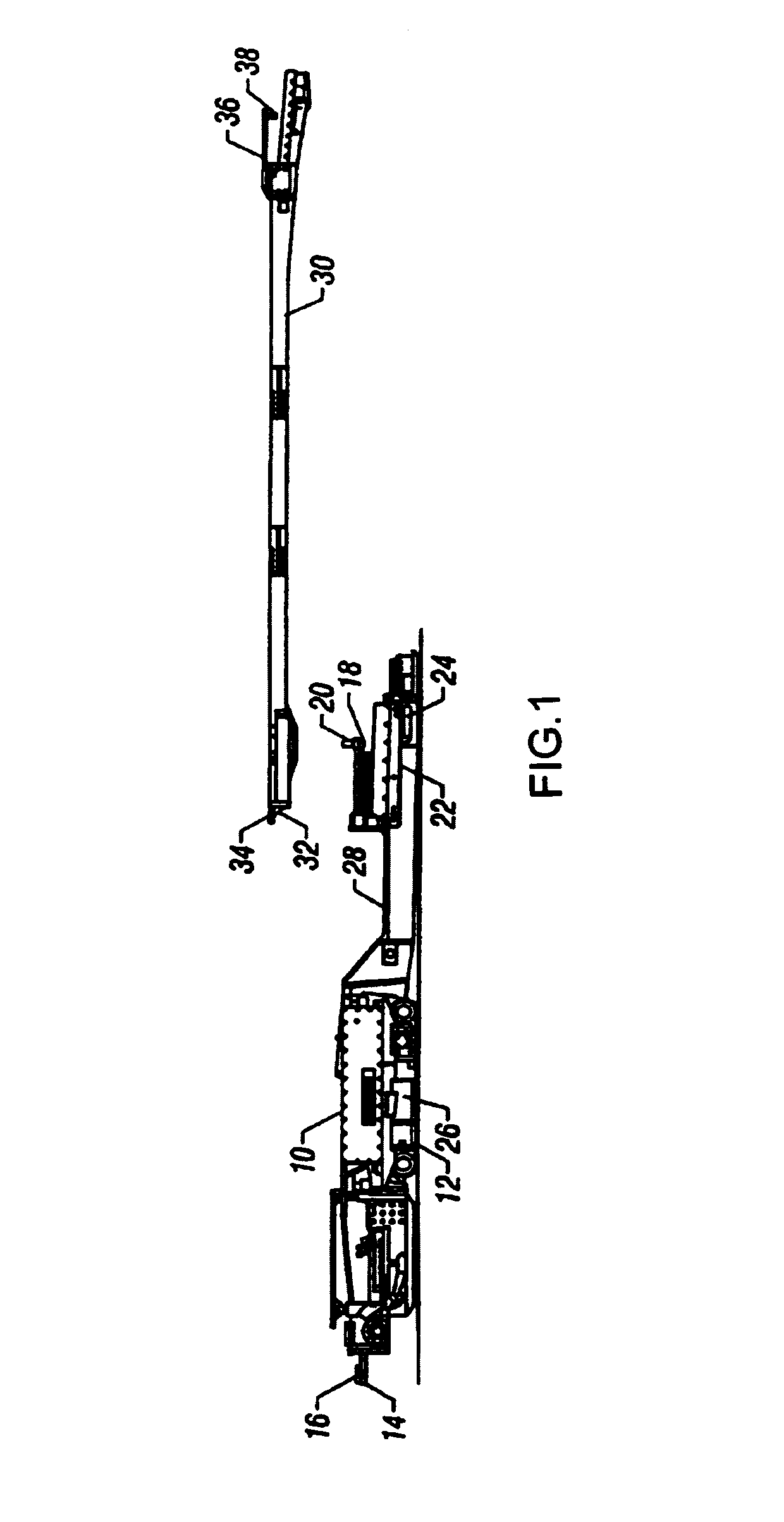
[0023]An exemplar mobile bridge carrier 10 and piggyback bridge conveyor 30 unit pair is illustrated in FIG. 1. The MBC 10 moves throu...


PUM


Abstract

The present invention relates to an automated continuous haulage apparatus and method designed for use in underground environments. Each mobile bridge carrier (10) contains distance measurement (70) and angular position (74) means for determining the mobile bridge carrier's (10) position and the angular position of attached piggyback conveyors (30). Means for determining the ceiling height (76) are utilized to adjust the height of the piggyback conveyors (30). On each mobile bridge carrier (10), input from the various sensors is received by an electronic controller (80) that calculates the position and orientation of the bridge carrier (10) and attached piggyback conveyors (30). The controller then plans an optimal path of movement for the bridge carrier (10) and computes the rate of movement for each independently operated track assembly on the bridge carrier such that the bridge carrier (10) and piggyback conveyors (30) arrive as close as possible to the planned path.

Description

[0001]This application claims the benefit of Provisional application Ser. No. 60 / 239,132, filed Oct. 10, 2000.BACKGROUND OF THE INVENTION[0002]1. Field of Invention[0003]The present invention relates generally to the automated control vehicles, and more particularly, to an apparatus and method for automating the operation of one or more underground mining vehicles used in continuous mining applications.[0004]2. Description of Prior Art[0005]When performing underground excavation, such as for example coal mining operations, it is desirable for efficiency purposes to continuously operate the mining apparatus breaking coal away from the face. In order to do so, means must be available for quickly and continuously hauling the loosened material from the mining site to an area remote from the mining site. One such continuous haulage system presently available and used in coal mines comprises a series of conveyor mechanisms pivotally linked together. The components of this system through t...

Claims


Application Information

Patent Timeline
Patent Type & Authority Patents(United States)
IPC IPC(8): G01M17/00E21C35/08G06F19/00G06F7/70E21F13/08G01S17/931
CPCE21F13/08E21F13/083G01S17/936G01S17/931
Inventor STURGES, ROBERT H.TWIGGER, MICHAELKANARAT, AMNART
Owner CATERPILLAR GLOBAL MINING LLC
Why Eureka
Try Eureka