Electrical supply or connecting terminal

a technology of electrical supply and connecting terminal, which is applied in the direction of coupling device connection, coupling device details, contact members penetrating/cutting insulation/cable strands, etc., and can solve the problems of not being able to ensure the reliability of electrical conductor contact, and being functionally relatively unimportan

Inactive Publication Date: 2006-08-01
PHOENIX CONTACT GMBH & CO KG
View PDF7 Cites 56 Cited by
  • Summary
  • Abstract
  • Description
  • Claims
  • Application Information

AI Technical Summary

Benefits of technology

[0008]Therefore, a primary object of this invention is to provide an electrical supply or connecting terminal of the initially described type which enables simple, but secure fixing of the clamping spring for a size as small as possible.
[0012]Loop-shaped clamping springs in electrical supply terminals or connecting terminals are basically known from the prior art, specifically as so-called tension springs in tension spring terminals. Tension spring terminals have become established on the market over time, in addition to screw terminals and recently also besides electrical terminals with insulation piercing terminal technology, and have been used millions of times especially as modular terminals. The advantage of tension spring terminals as compared to screw terminals is that the tension spring terminals enable faster and easier wiring. To actuate a tension spring terminal, only one actuating tool is necessary, for example, a screwdriver, which is pressed into the actuating shaft to open the terminal. In doing so, the tip of the screwdriver tensions the tension spring, by which the clamping site is open. A conductor which is to be connected can then be inserted through the recess into the clamping leg and after pulling out the screwdriver is clamped by the lower edge of the recess against a conductor bar which is connected to the tension spring.
[0014]According to one advantageous embodiment of the invention, the retaining section of the clamping spring is punched out of the contact leg and bent down. The retaining section corresponds to the material of the contact leg which is punched out of the contact leg when the recess is formed. Thus, the recess and the retaining section can be produced especially easily and in a material-saving manner by a punching and bending process. Moreover, because the contact leg and retaining section are in one piece, a further process step is not necessary for connecting the retaining section to the clamping spring.
[0015]According to another advantageous embodiment of the invention, the end of the conductor bar piece is bent down such that the end of the conductor bar piece, together with the end of the clamping leg of the clamping spring, form an inlet funnel for the electrical conductor to be connected. Thus, the execution of the inlet funnel automatically correctly positions the tip of an electrical conductor which has been pushed through the conductor inlet opening into the insulating housing so that simple and exact connection of the electrical conductor to the electrical supply or connecting terminal is possible.
[0016]As already stated, the electrical terminal means or connecting means is preferably made as a plug-in connector so that the metal part besides the conductor bar piece has a plug or socket part, the conductor bar piece and the plug or socket part being made in one piece so that the metal part can be altogether easily produced simply by punching and bending.
[0019]According to a another advantageous embodiment of the invention, which will be briefly mentioned here, the insulating housing has an actuating opening for insertion of an actuating tool, and on the clamping leg of the clamping spring, a kink is made which is aligned in the direction of the spring force of the clamping leg so that the tip of the actuating tool can act on the kink for opening the clamping spring. Providing an actuating opening for insertion of an actuating tool, first of all, results in that the electrical supply or connecting terminal can also be used for fine wire flexible conductors in which opening of the clamping spring simply by inserting the electrical conductor is not possible. Moreover, by opening the clamping spring using the actuating tool, an already clamped electrical conductor can be released from the clamping site. The kink made on the clamping leg enables easier action of the tip of the actuating tool on the clamping leg for opening the clamping spring.

Problems solved by technology

Whether in the individual case there is a terminal means or a connecting means, is functionally relatively unimportant.
When the clamping spring is opened with an actuating tool, there is the danger that the clamping spring will slip or the ends of its spring legs will even slip out of the opening so that proper positioning of the clamping spring when an electrical conductor is being inserted, and thus reliable contact-making of the electrical conductor are no longer guaranteed under certain circumstances.

Method used


Image

  • Electrical supply or connecting terminal
  • Electrical supply or connecting terminal
  • Electrical supply or connecting terminal

Examples


Embodiment Construction

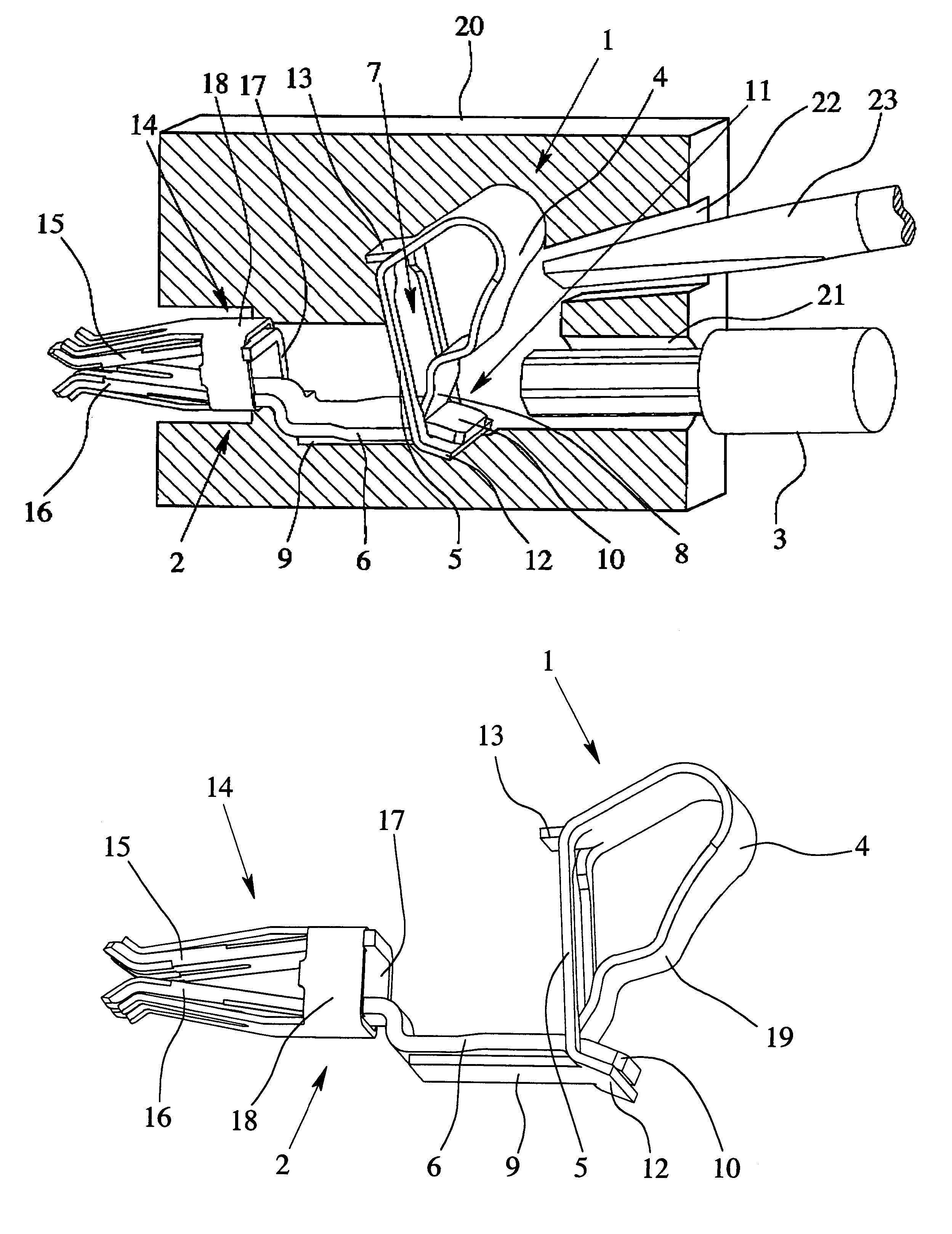
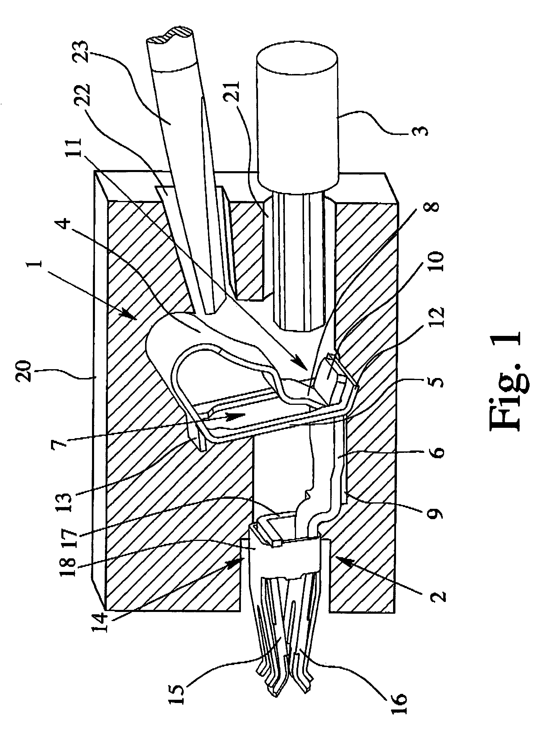
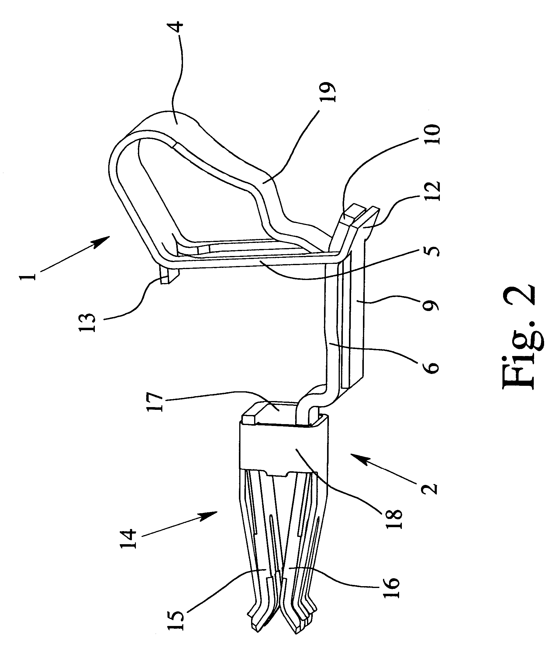
[0024]FIGS. 1 & 2 show a clamping spring 1 and a metal part 2 of an electrical supply or connecting terminal. The electrical supply or connecting terminal includes an insulating housing 20 having an inlet opening 21 for insertion of an electrical conductor 3 which is to be connected, and which is shown in FIG. 1. The clamping spring 1 has a clamping leg 4 and a contact leg 5. The clamping leg 4 and the contact leg 5 run roughly perpendicular to one another in adjoining portions. The metal part 2 has a conductor bar piece 6 and a socket part 14 which is joined integrally to the conductor bar piece 6.

[0025]As is especially apparent from FIGS. 1 & 3, in the contact leg 5 of the clamping spring 1, a recess 7 is formed into which the tip of the electrical conductor 3 to be connected can be inserted. In the state which is shown in the figures and in which the electrical conductor 3 is not yet connected to the electrical supply or connecting terminal, the end 8 of the clamping leg 4 extend...


PUM


Abstract

An electrical supply or connecting terminal with a clamping spring and a metal part, the clamping spring having a clamping leg and a contact leg, and the metal part having a conductor bar piece. The clamping leg and the conductor bar piece form a spring force clamp connection for the electrical conductor. The contact leg of the clamping spring has a recess for insertion of the electrical conductor, and an end of the clamping leg extends through the recess. The clamping spring has a retaining section which runs essentially parallel to the insertion direction of the electrical conductor and parallel to the conductor bar piece and the conductor bar piece has been inserted though the recess in a direction opposite the insertion direction of the electrical conductor, the conductor bar piece being clamped securely between the end of the clamping leg and the retaining section.

Description

BACKGROUND OF THE INVENTION[0001]1. Field of Invention[0002]The invention relates to an electrical supply or connecting terminal with a clamping spring and with a metal part, the clamping spring and the metal part being located in an insulating housing which has a conductor entry opening for entry of an electrical conductor which is to be connected, the clamping spring having a clamping leg and a contact leg and the metal part having at least one conductor bar piece, the clamping leg and the conductor bar piece forming a spring force terminal connection for the electrical conductor to be connected.[0003]2. Description of Related Art[0004]Electrical terminal means or connecting means are used to establish an electrical terminal or electrical connection, specifically to produce an electrically conductive connection, specifically a metallic connection, between a contact element and a mating contact element. Whether in the individual case there is a terminal means or a connecting means,...

Claims


Application Information

Patent Timeline
Patent Type & Authority Patents(United States)
IPC IPC(8): H01R4/24
CPCH01R4/4827H01R13/112H01R4/48275
Inventor STEINKEMPER, ANKEHOPPE, UDOGESKE, RALFHOLSTE, DIETERBEIER, THOMASLANGE, RALFKETTERN, MARKUSSCHAEFER, SEBASTIAN
Owner PHOENIX CONTACT GMBH & CO KG
Why Eureka
Try Eureka