
Mouse having a rotary dial

a rotary dial and mouse technology, applied in the field of mouse, can solve the problems of limited scrolling feature, user's inability to continuously turn the wheel, user's annoyance, etc., and achieve the effect of improving scrolling features

Inactive Publication Date: 2006-08-01
APPLE INC
View PDF141 Cites 336 Cited by
  • Summary
  • Abstract
  • Description
  • Claims
  • Application Information

AI Technical Summary

Benefits of technology

[0010]The invention relates, in another embodiment, to a computer mouse for moving a cursor or pointer on a display screen. The computer mouse includes a mouse housing. The computer mouse also includes a disk coupled to the mouse housing and rotatable about an axis. The disk is configured to facilitate a control function on the display screen. The disk has a touchable surface for rotating the disk about the axis. The touchable surface is completely accessible to a finger of the user such that the disk can be continuously rotated by a simple swirling motion of the finger.

Problems solved by technology

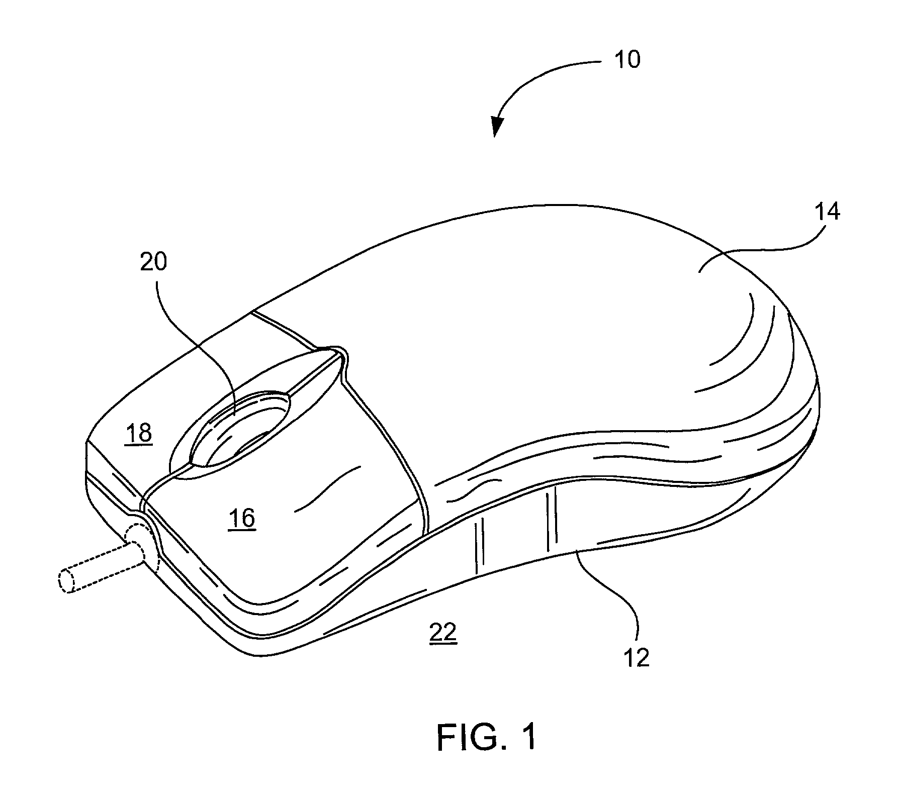
Unfortunately, the mouse described in FIG. 1 has several drawbacks.
For example, the scroll wheel is limited in that it only provides a single finger position for accessing the scroll wheel (e.g., same position for left and right handed users).
Furthermore, because only a small portion of the wheel can be used at any one time, the user cannot continuously turn the wheel.
This takes time and can be an annoyance to a user.
In addition, because a portion of the wheel protrudes above the top surface of the mouse, inadvertent or accidental scrolling may occur when one of the two buttons is activated.
Moreover, because the scroll wheel can only be manipulated in one direction, the use of the scroll wheel becomes counter intuitive when scrolling in a different direction in the GUI, as for example directions that are orthogonal thereto.
Also, the protruding scroll wheel is not aesthetically pleasing and thus it presents industrial design difficulties.

Method used


Image

  • Mouse having a rotary dial
  • Mouse having a rotary dial
  • Mouse having a rotary dial

Examples


Embodiment Construction

[0024]Embodiments of the invention are discussed below with reference to FIGS. 2–10. However, those skilled in the art will readily appreciate that the detailed description given herein with respect to these figures is for explanatory purposes as the invention extends beyond these limited embodiments.

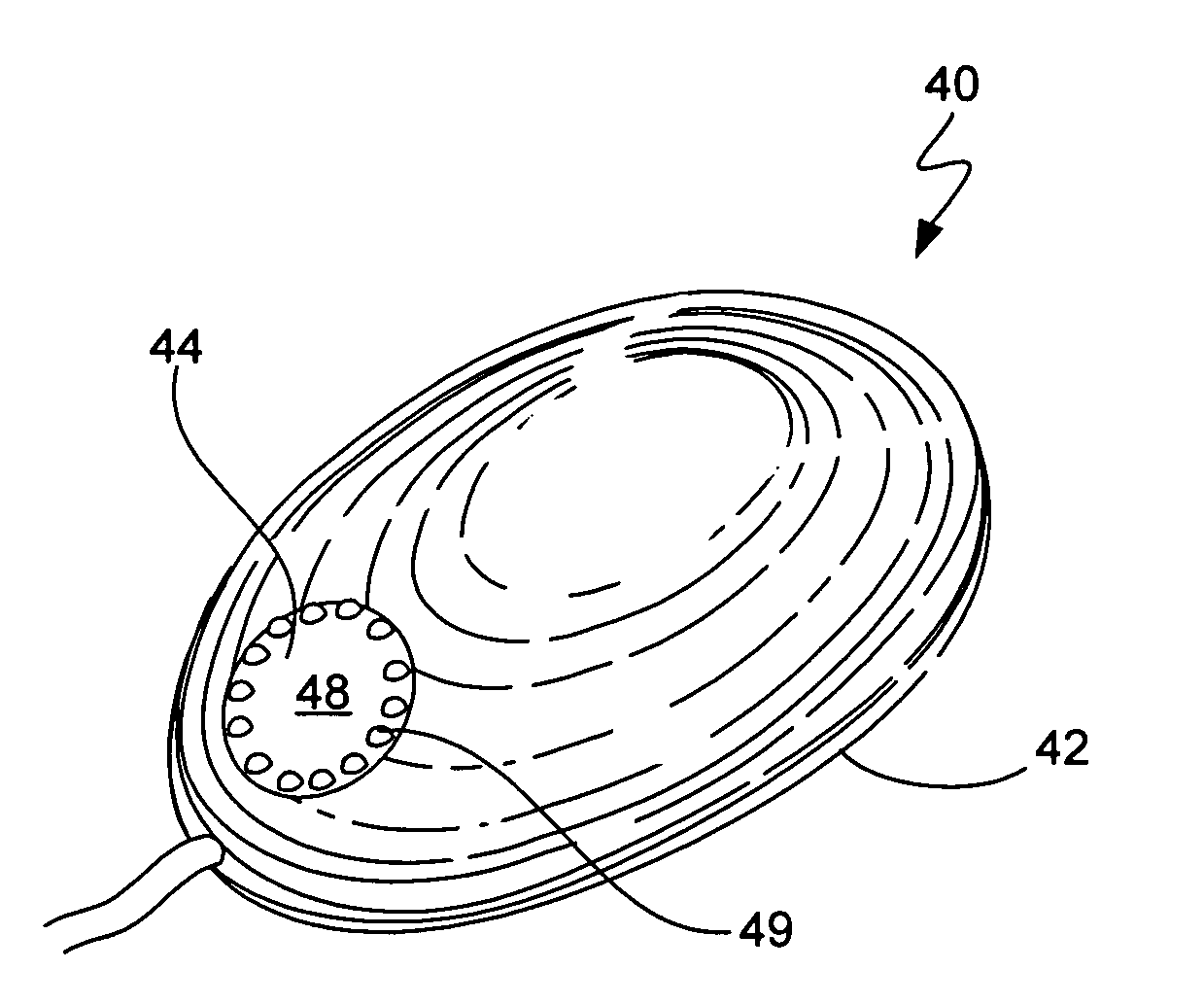
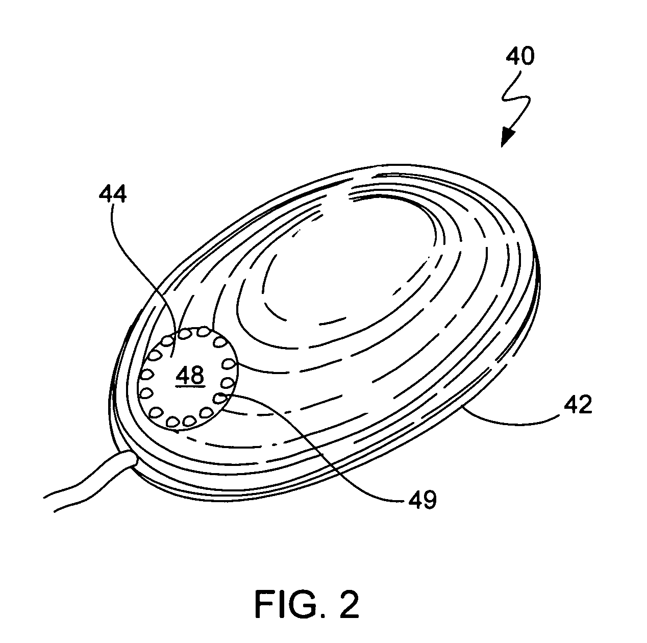
[0025]FIG. 2 is a perspective diagram of a mouse 40, in accordance with one embodiment of the invention. The mouse 40 is a user operated input device for moving a cursor or pointer on a display screen. By way of example, the input pointer may be displayed via a Graphical User Interface (GUI) on a display screen. In general, the mouse 40 is configured to provide positional information, which corresponds to the movement of the mouse along a surface, to a computer system that includes the display screen. The positional information is used by the computer system to move the cursor or pointer on the display screen of the display monitor. For example, when the mouse is moved forward, the curs...


PUM


Abstract

A user operated input device is disclosed. The user operated input device includes a housing and a rotary dial positioned relative to an external surface of the housing. The rotary dial provides a control function.

Description

CROSS REFERENCE TO RELATED APPLICATION[0001]This application claims the benefit of U.S. Provisional Application No. 60 / 345,325, filed on Oct. 22, 2001, entitled “Mouse Having a Scrolling Feature”, in which the disclosure is incorporated herein by reference. This application is also related to U.S. Patent Application No. 60 / 346,237, entitled “Method and System for List Scrolling”, filed on even date and which is incorporated herein by reference.BACKGROUND OF THE INVENTION[0002]1. Field of the Invention[0003]The present invention relates generally to a mouse for use in a computer system. More particularly, the present invention relates to scrolling features for a mouse.[0004]2. Description of the Related Art[0005]Most computer systems, as for example general purpose computers such as portable computers and desktop computers, receive input from a user via an input device such as a mouse. As is generally well known, the mouse allows a user to move an input pointer and to make selections...

Claims


Application Information

Patent Timeline
Patent Type & Authority Patents(United States)
IPC IPC(8): G09G5/08G06F1/16
CPCG06F3/0362G06F3/03543
Inventor HUPPI, BRIAN
Owner APPLE INC
Learn More